User Tools

Site Tools


en:sat:station6

QO-100 Station Version 6

these records are mainly for documentation, but maybe there is a good idea for some readers.

Scope of functions

The station should have the following features:

  • NB operation via SDR (Pluto)
  • NB operation via TRX (IC9700)
  • NB WebSDR with spectrum and waterfall and audio
  • WB transmit via Pluto
  • WB receive with minitiouner
  • WB WebSDR with spectrum and waterfall
  • all components GPS synchronized
  • Supply and clock for the LNB
  • output power 5 Watt

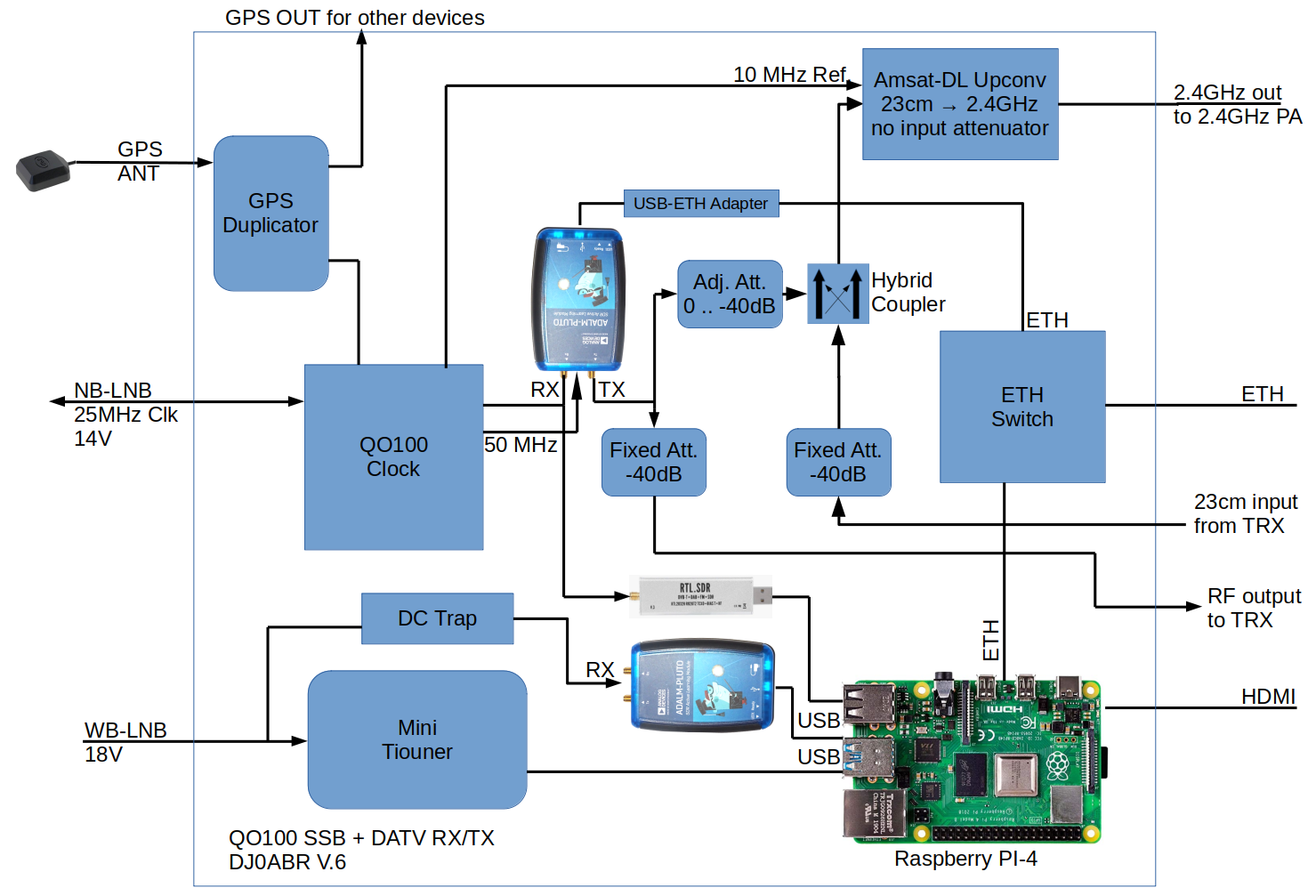
Block diagram

above requirements are met by this hardware:

QO100 Clock

all clocks are generated by this board: QO100: clock and supply for LNB and Pluto

The following clocks are generated from the GPS stabilized reference clock:

  1. 25 MHz for the LNB (supply via phantom power in the sat-cable).
  2. 50 MHz for the NB Pluto
  3. 10 MHz for the upconverter
  4. 10 MHz for the IC9700

NB operation via SDR (Pluto)

The SDR software accesses the NB-Pluto via Ethernet. This is connected with a USB/ETH adapter and has a fixed IP address.

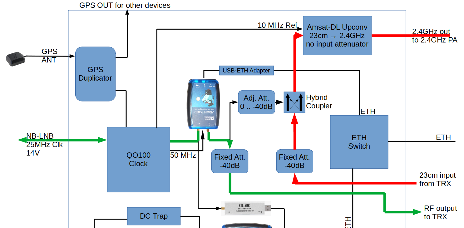
The receive signal (green) comes from the LNB and goes through the clock board, where 13.8V supply as well as the 25 MHz LNB clock are fed. Finally, the receive signal is fed to the RX input of the Pluto.

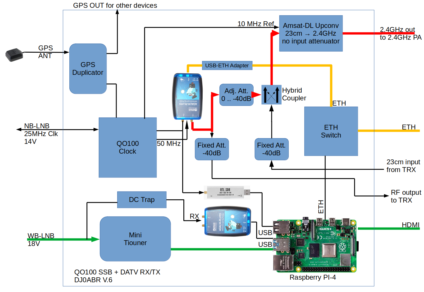
The transmit signal (red) is generated by the Pluto and output at the TX connector. This is followed by an adjustable attenuator 0–40dB, which is especially helpful for DATV. After the attenuator it goes via a hybrid coupler to the transmitter mixer (Amsat-DL upconverter) which mixes the signal to 2.4GHz and amplifies it to 6W.

NB operation via TRX (IC-9700)

The receive signal (green) comes from the LNB and goes through the clock board where 13.8V supply is fed as well as the 25 MHz LNB clock. Finally, the receive signal is fed to the RX input of the Pluto. This is the same as before in SDR mode.

A Crossband repeater software is now started for the Pluto. This causes the Pluto to receive the signal on 739MHz and retransmit it at its TX output in the 70cm band, unchanged. Via a 40dB attenuator the received signal is finally passed on to the TRX (receiver) and can be heard in the 70cm band.

The transmit signal (red) comes from the transceiver and goes via a 40dB attenuator and the hybrid coupler to the transmitter mixer (Amsat-DL upconverter) which mixes the signal to 2.4GHz and amplifies it to 6W.

WB (DATV) operation

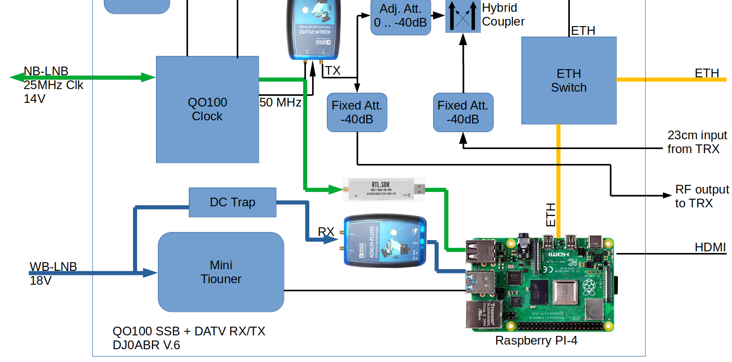
The receive signal (green) goes from the LNB to the minitiouner, which also generates the 18V supply for the LNB.

Connected to it is a Raspberry PI-4 with the Ryde software (BATC), the video is output at the HDMI connector.

The broadcast signal is generated from any streaming source (e.g. OBS software) and fed via Ethernet directly into the Pluto, which generates the final DATV signal. The transmit path is then identical to NB operation, i.e. via attenuator and coupler to the transmit mixer.

WebSDR NB and WB

The signal from the NB transponder is fed to an RTLSDR stick, the signal from the WB transponder to a second Pluto (because of the high bandwidth). Both SDRs are connected to the Raspberry PI 4 via USB. In the Raspberry the WebSDR runs twice, once in NB version and once in WB version.

The Raspberry offers spectrum and waterfall via its integrated web server:

http://IPaddressRaspi/nb.html

and

http://IPaddressRaspi/wb.html

This website uses cookies. By using the website, you agree with storing cookies on your computer. Also you acknowledge that you have read and understand our Privacy Policy. If you do not agree leave the website.More information about cookies
en/sat/station6.txt · Last modified: 2022/04/05 19:47 by kurt