Sidebar
Table of Contents
DSP-7-PA
Controller for amateur radio power amplifiers with large 7" TFT touch color display
and many measurement functions, sensors and WiFi webinterface
Overview
The DSP-7 board can be used as a controller for amateur radio amplifiers (lowband, shortwave, VHF / UHF / SHF) and also as a display for power / SWR meters (simultaneous single, dual or triple SWR bridge).
This description focuses on the DSP7-7-PA, which is used as a power amplifier controller. It supports most home-built amplifiers, making it a professional product that outperforms most commercial power amplifiers in functionality and safety.
These are only three examples from the 14 screen menus:
User interface: display of power / SWR measurement
- Large 7 “TFT color touch screen with SD card slot
- Many convenient screens display measurement values and amplifier status
- Color bar graphs and data as numerical values
- Photo realistic power / SWR meter simulation of a cross pointer instrument
- history graph, selectable recording times
- three power/SWR measurements: at input, between amplifier and filter, and at output
- works with all AD8307-based power / SWR couplers (even home-made) via software calibration
user interface: analog measurements
- temperature-1: temperature of the power transistor
- Temperature-2: Temperature of the heat sink
- Supply voltage (four selectable ranges from 50V to 4kV)
- Supply current (four selectable ranges from 10A to 200A)
- Frequency measurement 100kHz to 60 MHz
- DC input power
- Amplifier efficiency
User interface: amplifier control
- ON switch: by touch key or external key
- STANDBY: by touch key or external key
- ACTIVE: by touch key or external key
- EMERGENCY OFF: by touch key or external key
Switching functions:
- PTT control
- BIAS on / off (deactivates the bias of the amplifier in case of error)
- Fan or water pump control
- DC power supply control
- Power supply safety circuit control
- ALC monitors current consumption to limit control power and is therefore independent of SWR
Band and antenna selection:
- band selection via touch key or external rotary switch
- automatic selection of up to 3 antennas, convenient assignment of bands to antennas
- automatic band and antenna selection for ICOM transceivers
Safety functions:
- monitoring of the supply voltage, complete shutdown in case of a fault
- monitoring of supply current, complete shutdown in case of error
- Temperature measurement: automatic switching on / off of the fan and deactivation of TX, if an adjustable limit value is exceeded
- Control of the transceiver via ALC to reduce the control power
- Monitor control power and switch to standby mode when limit is exceeded
- Monitoring of SWR between amplifier and low pass filter, switching off if wrong filter selection is made
- Monitoring the antenna SWR. If worse than 2: 1 then RX mode, if worse than 3: 1 emergency shutdown.
W-lan:
- Integrated WiFi interface
- AP mode (WLan access point)
- Client mode
- integrated web server
- display of measured values and amplifier status
- can be displayed on PCs and smartphones using a web browser
Other:
- serial CI / V interface to read out the tape from Icom devices
- RS232 interface for firmware updates
- user can update many images with own graphics with SD card
- powerful ARM Cortex 3/4 miccontroller with 1MB flash
- DC power supply: 10-15 volts, 250mA
- Controller and display is one compact unit, easy mounting on front panels
- RF tested 4-layer board, inputs with EMI ferrites and capacitors
- own full size ground plane
- own power supply layers
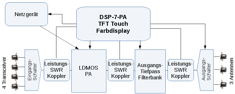
Block diagram of a complete power amplifier with this controller:
Input and output switches are optional, but extremely convenient as they switch in a completely automated fashion.
At the input, a coupler monitors the input power; if it is too high (transceiver accidentally set to full 100W), the output stage is switched off. A second coupler monitors the impedance between the power amplifier and the low pass filter. If this is too high (e.g. wrong filter) the output stage is switched off. The third coupler measures output power and antenna SWR.
The filter bank with low pass filters is switched automatically, depending on the selected band. With CAT interface the band is read out from the transceiver.
Furthermore DSP-7-PA monitors the power supply and the temperature to switch off in case of error.


