User Tools

Site Tools


en:sat:filter2400

2.4 GHz High Power Low Pass Filter

Coaxial Filter

After the DATV power amplifier is finished and in operation I had to notice that I plug the LNB at powers >20Watt. Apparently there is still interference from the 4th harmonic. That was the reason to build a low pass filter. Of course, this must also withstand the power of up to 75W, which is why conventional components are out of the question.

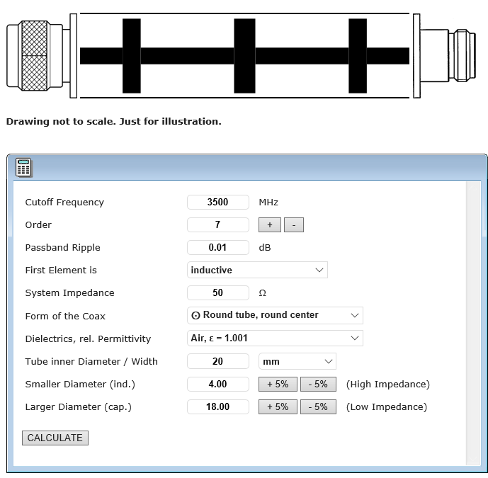
On inquiry in the AMSAT forum DH2VA gave me a link to G4DBN, who already built a coaxial filter for 23cm. He had used a (French) Excel spreadsheet from F1FRV to calculate the dimensions of the filter. I used the online calculator from changpuak.ch for the design, which gives similar results but is in English.

I set the cutoff frequency to 3.5 GHz. A bit high, but I wanted to avoid that it slips too low due to tolerances in the setup. A few dB worse filter effect I gladly accept if only the pass through attenuation is as low as possible. With these performances one must be stingy with every tenth dB.

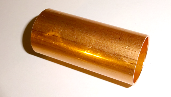
The whole thing is installed in a copper water pipe from the hardware store. This has an inner diameter of 20mm.

As smallest diameter for the filter measuring part I have chosen 4mm. So I can bring the connections of the N-connectors/sockets just still into an appropriate drilling.

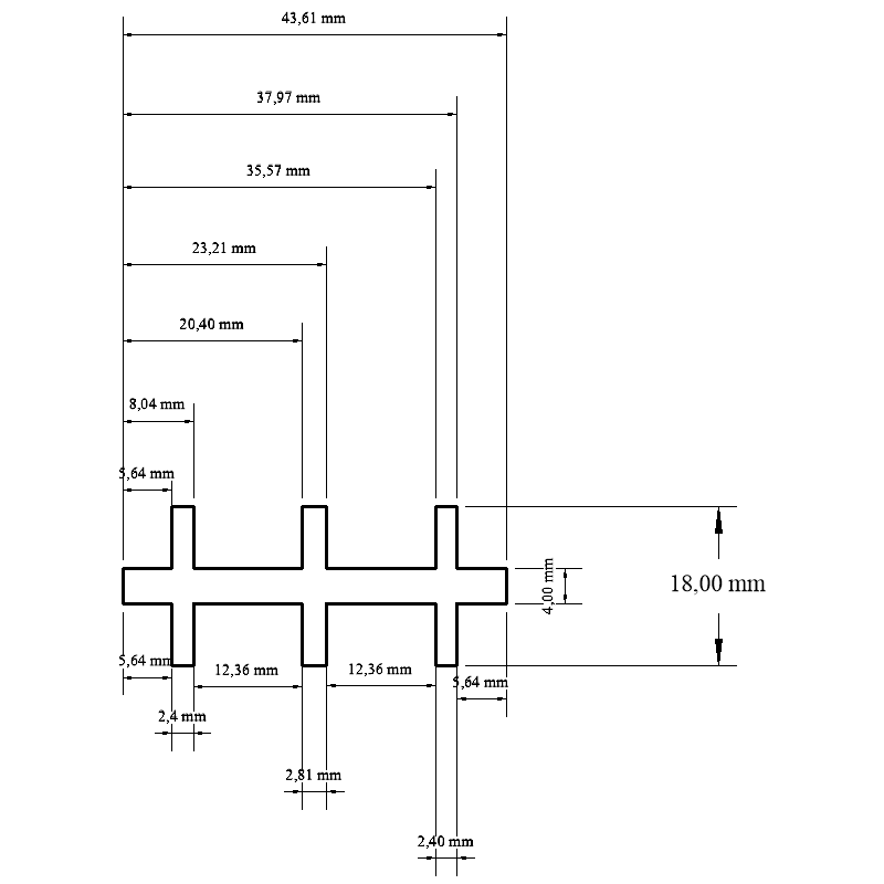
With the above inputs, the dimensions are calculated as follows:

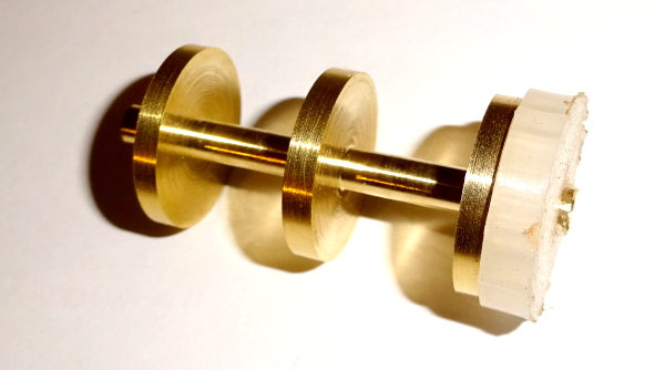
This rotary part was built by DL1EV, for which I would like to thank again. Here we are talking about hundredths and the dimensions are quite correct.

The following parts are needed:

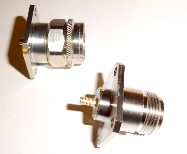
flange connector and flange bushing. The selection of flange connectors is very clear, I was glad to have found one at all. Both connectors are from Telegärtner, not exactly a bargain, but good quality, except that the inner conductor is not gold-plated, which I would have expected for a connector > 10 Eur. The flange socket has a M3 thread on the inner conductor. This is necessary, because you can't solder the second connector.

a suitably cut to length water pipe. I made it 0.2mm too long so that there would be a good press fit after assembly.

and the inner part made by DL1EV, on one side a spacer made of PP (3D printed) is already attached.

These spacers are absolutely necessary. If the part is not centered exactly in the tube, the filter will not work at all.

Assembly:

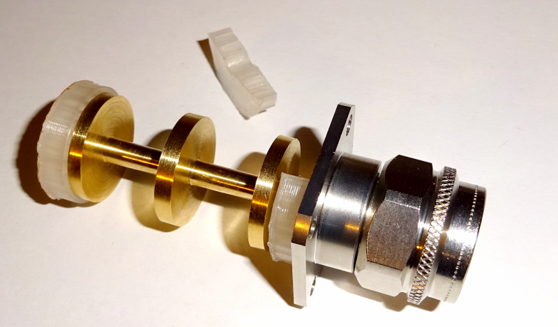
First, I soldered the flange plug into the matching hole on the inner part and then put the spacer washer on the front.

Of course, you can't put the spacer washer on the flange plug anymore, so I separated it into two parts with a box cutter and then put it on top.

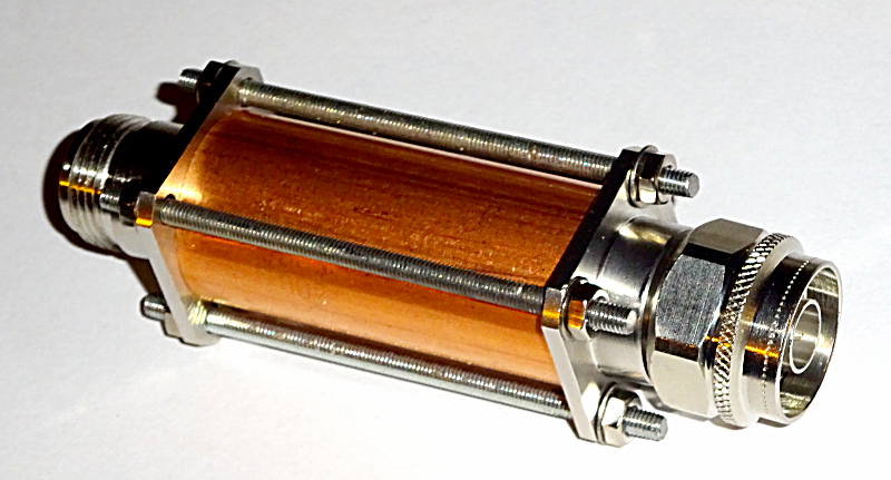
finally, the whole thing was pushed into the pipe and the flange socket was screwed on until it was hand-tight.

finally the whole thing was screwed tight with four threaded rods.

Between plug and tube the ground is only given by a clamping. This doesn't really excite me, but it can't be done any other way. I hope the long-term stability of the filter does not suffer from this clamping.

Measurements:

Now it becomes difficult, since my measuring possibilities go only up to 3 GHz.

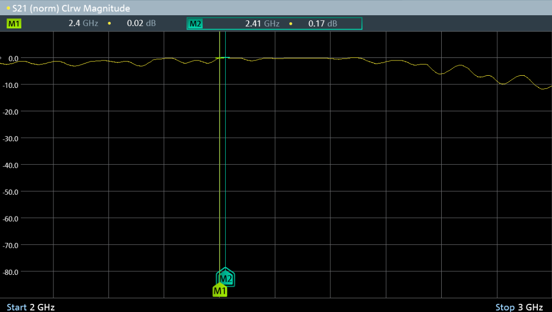
Therefore I first measured the insertion loss:

this was measured with 0.02 to 0.17 dB. One must admit, however, that such small attenuations can no longer be measured precisely, unless one has an analyzer of the price of a single-family house.

I calculate with 0.2dB. What does that mean for a transmitting power of 75 watts: Due to the attenuation of 0.2dB, one loses 2.6 watts. I think this is not a problem.

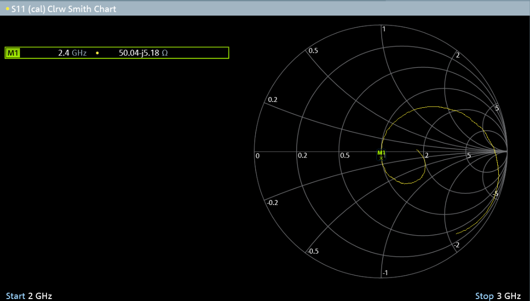
What about the matching:

this is at 65 ohms, but has a capacitive component. This is probably the reason for the ripple seen above. After a tip from Alois, DL8RAM, I went searching and found the cause to be the spacer rings. They are made of PP (polypropylene), a material that practically does not react to 2.4GHz, but it has different dielectric properties than air, which leads to the poor matching.

So I removed the rings and made the gap by thin cardboard strips. These strips have virtually the same properties as air, at least as long as they stay dry.

Now the whole thing looks like this:

50 ohms and only a tiny capacitive component, which corresponds to an input SWR of 1.1 : 1, or a return loss of 26dB. So it fits.

However, one thing is puzzling to me: The filter has just on 2.4 GHz the optimal adjustment. This was not intended. Actually, it should have good matching everywhere on all frequencies below about 2.8 GHz. Something is wrong. Apparently there is resonance within the filter just above 2.4GHz, this just fits, lucky.

Still, this needs further investigation. I will give the filter to an OM who can measure up to 10 GHz. As soon as I have results I will show them here.

This website uses cookies. By using the website, you agree with storing cookies on your computer. Also you acknowledge that you have read and understand our Privacy Policy. If you do not agree leave the website.More information about cookies
en/sat/filter2400.txt · Last modified: 2021/06/15 00:41 by kurt