User Tools

Site Tools


en:sat:plutolnb

QO100: Clock and supply for LNB and Pluto

Version 4B

for the home station as well as a portable setup we want to minimize the wiring as good as possible.

What we always need:

  1. Power supply for the LNB via the sat-cable (usually 14V, but 12 to 13,8V is fine)
  2. stable 25 MHz reference frequency for the LNB (via the sat-cable or via separate cable)
  3. stable reference frequency for the Pluto
  4. optional: 10 MHz reference output for TRX (IC9700) or frequency counter

the following circuit solves this task.

Power is supplied from the station power supply or the car battery with 13.8 volts (12V).

The reference clock is generated with a high precision OCXO, which can be optionally GPS stabilized.

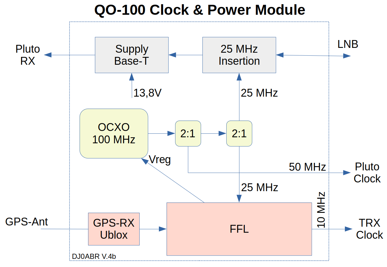
Block diagram:

Clock generation:

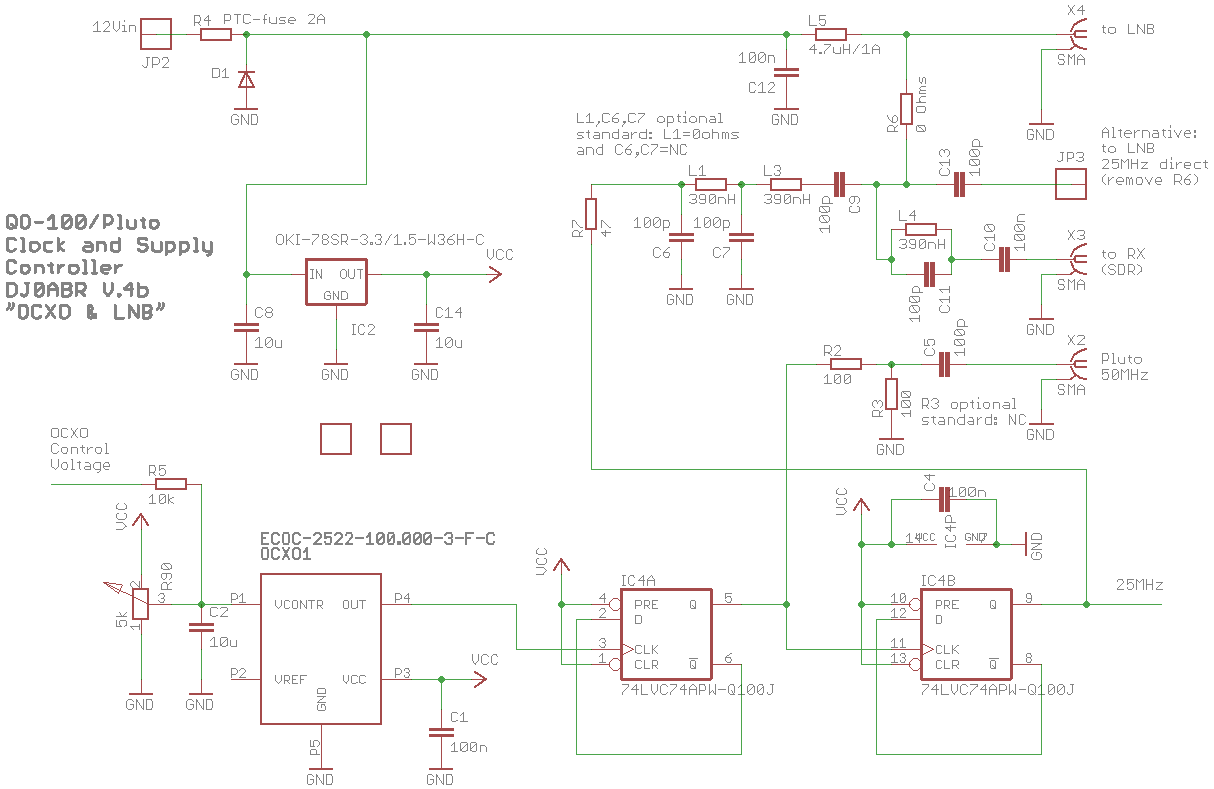
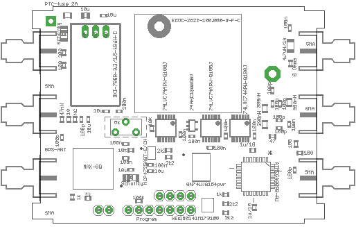
On the board (which fits into a common 74x55mm tinplate case) is an SMA connector for connecting the sat cable. This is connected to an SMA socket for the receiver. The LNB supply is fed via a 4.7uH choke (phantom power). At a voltage of 13.8 or 12V the LNB switches to polarization for the NB transponder of QO-100.

The OCXO ECOC-2522-10.000-3-F-C (available e.g. at Digikey) is comparatively very inexpensive. Yes, of course, it costs quite a bit, but compared to its excellent data, the price is okay. It is so precise that you don't need a GPS connection. Nevertheless, a GPS correction has been provided as an option, but it does not need to be equipped.

Availability: since exactly this OCXO is not always available, there are identical OCXOs from other manufacturers, see: Abracon AOCJY-100.000MHZ, from e.g. Mouser, different options (whereas types without SW are to be preferred), which should all work, SMD and also wired types can be mounted on the PCB. The Abracon OCXO was not tested by me, but according to the data sheet it should work just as well.

The OCXO generates the reference frequency of 100 MHz. With the first divider 50 MHz is generated to supply a pluto and with a second divider 25 MHz to supply the LNB.

The 50 MHz signal is lowered in level for the Pluto and output on a SMA connector. For the LNB, the 25 MHz signal is filtered and can then either be fed into the satellite cable, or it can be tapped at its own soldering point.

Normally, the 25 MHz will be routed through the satellite cable to minimize the amount of wiring. For this purpose a decoupling filter is installed in the LNB.

Using the example of a Megasat LNB, the installation is described here: LNB conversion

The internal supply voltage of 3.3v is generated with a small step-down converter. This is pin compatible with the well known 78xx. If a 78xx type is used, it has to be cooled, while the step-down converter does not need cooling.

GPS receiver:

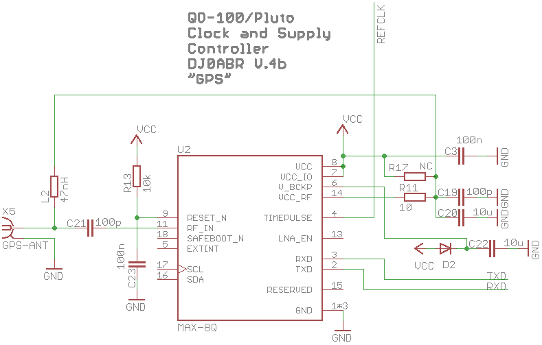
an Ublox MAX-8Q is used. This module is inexpensive and has a programmable reference output (10 MHz).
The highly jittering 10 MHz signal is used by the FFL for stabilization.

Via the serial interface the Ublox module is set to output the reference frequency when the GPS receive signal is valid.

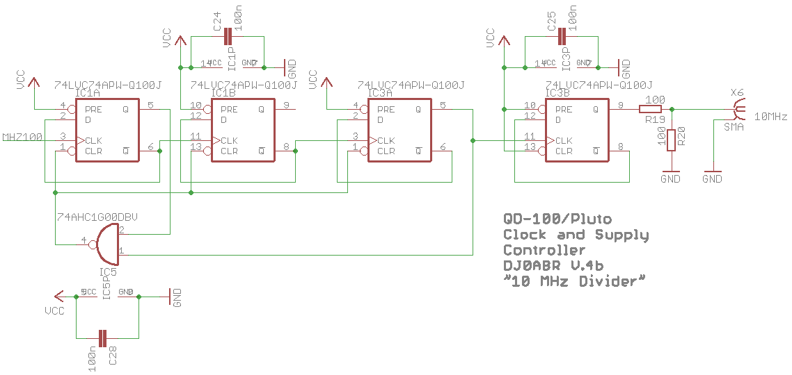
divider 10 : 1

10 MHz is generated from the 100 MHz OCXO. This frequency can be used for a transceiver (e.g. IC9700) or also frequency counters, etc.

FFL (Frequency Locked Loop):

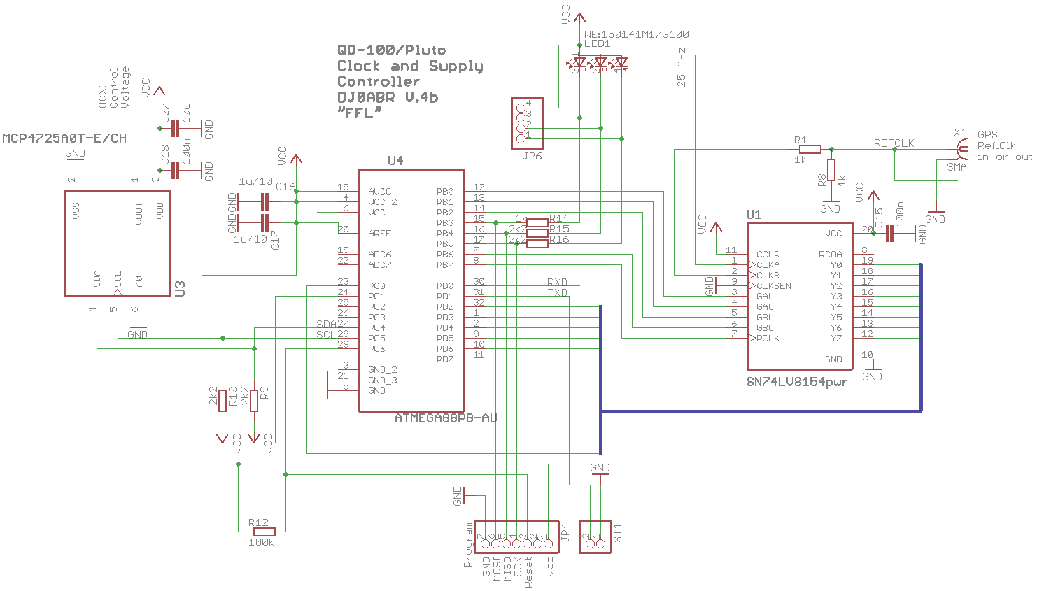
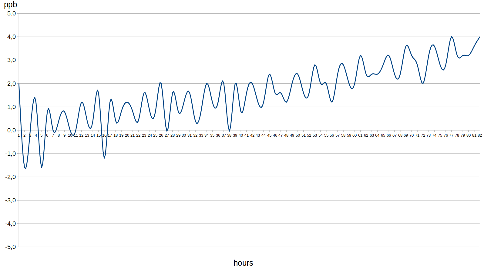
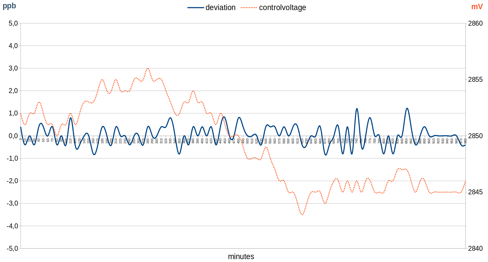
A 16 bit counter is used to count both the 25 MHz LNB clock and the 10 MHz reference signal. By comparing both signals by software, the actual frequency of the 25 MHz signal is measured, with an accuracy of 0.01Hz. From the deviation a correction value is formed, which fine tunes the OCXO via a 12bit DAC as control voltage.

The 74LV8154 is needed because the uC is not fast enough to count 25 MHz directly. Every 2ms the count is read and then added to the full count value by software.

the board:

the PCB is designed for a tinplate case 72x55mm.

Pluto clock conversion

to make the Pluto work with 50 MHz it has to be switched. See here: Pluto clock

Connection of the Pluto:

An Adalm Pluto Rev.C can be connected directly to connector X2. If not already done, you need a SMA-U.Fl adapter cable for the Pluto Rev.C.

Connection of the LNB:

the LNB is supplied with the required voltage for vertical polarization (SSB operation). In addition, the 25 MHz reference is fed into the satellite cable via R6, which is decoupled in the LNB (Amsat-DL modification).

If you have a LNB without this decoupling, you can also tap the 25 MHz at JP3 and lead it via a separate cable to the LNB.

Receiver connection

A SDR receiver is connected to X3. Here only the pure receive signal in the range of approx. 739 MHz is present. So you need a SDR like the Pluto. For connection to normal radios a suitable mixer would have to be connected.

Operation without GPS:

One equips the potentiometer R90. The ICs U1, U3 and U4 and the corresponding components are not needed and remain free.

After the assembly one measures at the 50 MHz connection with a good frequency counter. With the potentiometer you adjust to exactly 50 MHz. The OCXO has a low aging, so it can be operated for several months without further adjustment. For normal applications on QO-100 it does not need to be adjusted at all. Even after years, the deviation is only a few kHz of the QO-100 receive frequency.

Operation with GPS:

In this case everything is equipped. At the first start-up the potentiometer must be calibrated. To do this, connect the MISO and MOSI lines to pin header JP4, then switch on. Measure the 50 MHz output with a frequency counter and adjust the potentiometer as good as possible to 50 MHz. Then switch off and remove the jumper.

Note that the complete synchronization process can take at least 5 to 10 minutes or longer. With this long loop time you have no additional phase noise and also become independent of the short term quality of the GPS reference (a GPS receiver has excellent long term accuracy but poor short term jitter).

LEDs:

red … Power indicator. Lights up after a few seconds as soon as the system is ready for operation.

blue … (only with GPS) lights up as soon as the OCXO is close to the target frequency. Radio operation is now already possible.

green … (only with GPS) lights up as soon as the OCXO has reached an accuracy of better than 0.4ppb at least once, GPS lock exists.

Tips:

if the length of the SAT cable to the LNB is very long (several 10m), the level of the 25 MHz clock can become too small. In this case C6 and C7 are not populated and L1 is replaced by a solder bridge. For extremely long cables you can also replace R6 and R7 with solder bridges, which was necessary for my 80m long SAT cable.

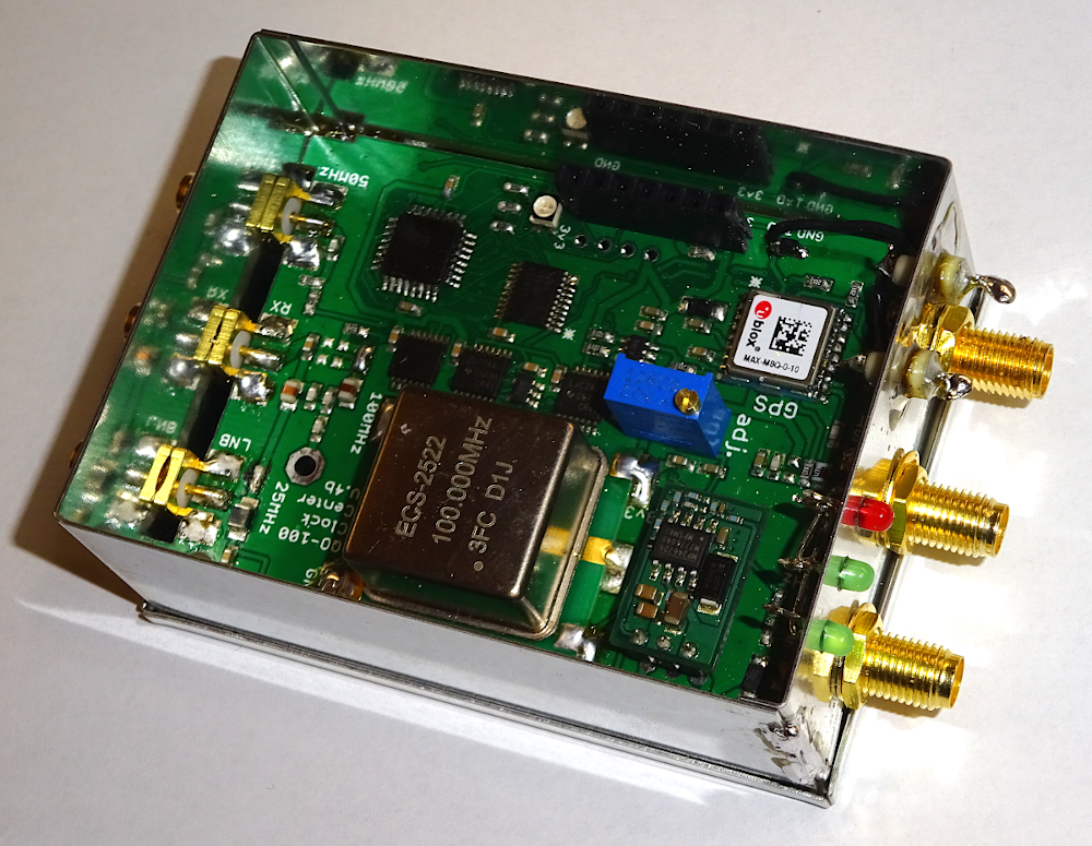
ready assembled device:

Measurements:


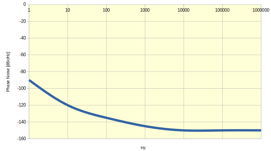
Phase Noise


free running OCXO, still in run-in phase


GPS stabilized OCXO

Downloads:

Eagle Schematics and PCB files

qo100clock4b.sch.zip

qo100clock4b.brd.zip

To compile the firmware you need a full installation of avr-gcc (see “comp”), for flashing you need avrdude (see “prg”).

uC and firmware is only required for GPS operation. Pure OCXO operation does not need a microcontroller.

ocxo_firmware.zip

This website uses cookies. By using the website, you agree with storing cookies on your computer. Also you acknowledge that you have read and understand our Privacy Policy. If you do not agree leave the website.More information about cookies
en/sat/plutolnb.txt · Last modified: 2024/10/14 13:19 by kurt