Sidebar
Table of Contents
DSP-7-PA
Controller for amateur radio power amplifiers with large 7" TFT touch color display
and many measurement functions, sensors and WiFi webinterface
Connections
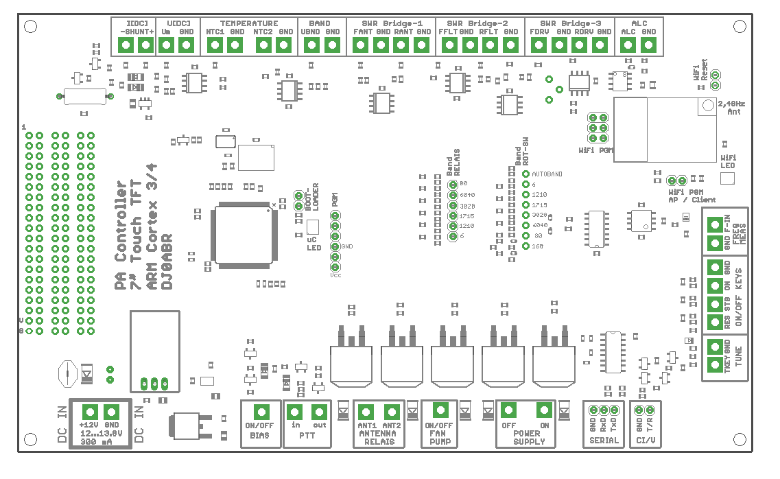
The DSP-7-PA board is clearly labeled on all connectors. Here is the list of connectors and their use, starting at the top left and going clockwise:
| Function | Connection | Description |
| I[DC] | - SHUNT | If you want to measure a current of the e.g. station supply, you insert a shunt resistor into the positive supply line. This pin is connected to the shunt on the side facing the power supply. See note-2 |
| + SHUNT | and this to the side pointing to the load. | |
| U[DC] | Um, GND | Voltage measurement input. This connector can be connected to a positive voltage (up to 100V) to make a voltage measurement, e.g. of the station power supply. See note-3 |
| TEMPERATURE | NTC1, GND | Temperature measurement-1: for this you connect here a NTC Type: B57703M103G (10kohms) |
| NTC2. GND | Temperature measurement-2: to connect an NTC Type: B57703M103G (10kohms) here | |
| BAND | UBND, GND | ICOM devices output a voltage whose level corresponds to the selected band. This function can be used alternatively to the CI/V interface to use the automatic band/antenna switching. |
| SWR Bridge-1 | FANT, GND | connect to measurement coupler-1 with its output of the leading power, see note-1 |
| RANT, GND | connect to measurement coupler-1 with its output of the returning power, see note-1 | |
| SWR Bridge-2 | FFLT, GND | connect to measurement coupler-2 with its output of the forward power, see note-1 |
| RFLT, GND | connect to measurement coupler-2 with its output of the returning power, see Note-1 | |
| SWR Bridge-3 | FDRV, GND | connect to measurement coupler-3 with its output of the forward power, see note-1 |
| RDRV, GND | connect to measurement coupler-3 with its output of the returning power, see note-1 | |
| ALC, GND | ALC output to reduce the control power of the transceiver, depending on the current consumption of the PA (adjustable). | |
| FREQ MEAS | F_IN, GND | connect this terminal via a suitable coupling capacitor (e.g. 10pF) to the transceiver antenna terminal to measure the frequency. |
| EMERGENCY STOP | RES | an emergency stop button can be connected here. If a relay is used to switch the station power supply on/off, it can be switched off here. The same function can be performed via touch keys on the display. |
| STB | A pushbutton can be connected here. Each press of the button switches between active mode and standby. The same function can be executed via touch keys on the display. | |
| SWITCH ON | ON | A switch-on pushbutton can be connected here to start the power supply after switching on or after an emergency stop. If a relay is used to switch the station power supply on/off, it can be switched off here. The same function can be executed via touch keys on the display. |
| TKEY | can be connected to the TKEY line of an Icom device. As soon as the Icom transceiver is in tuning mode, the power amplifier is switched off. | |
| CI/V | T/R, GND | Icom CI/V Interface. If this connector is connected to an ICOM transceiver, the tuned frequency is read out and the matching antenna is switched on (if an antenna switch is available). |
| SERIAL | RxD, TxD, GND | Universal RS-232 interface. Used to flash new firmware versions into this device. |
| POWER SUPPLY | ON | After power on this connector goes to GND. You can connect a relay (against +12V) to switch on the station power supply. As soon as you switch to “active” the connection becomes high impedance again. See note-5. |
| OFF | in normal operation this connection is high impedance. You can connect a relay (against +12V) here. If an emergency stop situation is detected, this terminal goes to GND and the relay picks up. See note-5. | |
| FAN, PUMP | ON/OFF | as soon as a set temperature is exceeded, this connection goes to ground. A 12V relay can be connected directly (against +12V) to e.g. switch on a fan. |
| ANTENNA RELAY | ANT1 | Connector for an antenna relay, see note-4 |
| ANT2 | Connector for a second antenna relay, see Note-4 | |
| PTT in | is connected to the PTT output of a transceiver (open=RX, GND=TX) | |
| PTT out | is connected to the PTT input of the power amplifier (open=RX, GND=TX) | |
| BIAS ON/OFF | +12V output can be used as BIAS supply for the power amplifier. Will be switched on only during transmission. | |
| 12..13,8V | +12V, GND | Power supply of this device incl. display. Here a voltage between 8 and 15 volts must be connected. |
additional pin headers in the middle of the board:
| Function | Connection | Description |
| BAND RELAY | 80 | Connection to a relay (via a driver transistor) to activate the corresponding band in the output filter. This output goes to 3.3V when activated. When no output is active, the 160m band is selected. These outputs can have 4 different band configurations which are selectable in the SYSTEM menu of the firmware, so most different filter-band combinations are possible. |
| 60/40 | ||
| 30/20 | ||
| 17/15 | ||
| 12/10 | ||
| 6 | ||
| BAND RED SWITCH | 160 | These pins can be connected to a rotary switch (common pin of this switch with GND). When connected, the band can be selected with this switch. When not connected, the bands can be selected by touch keys on the display. |
| 80 | ||
| 60/40 | ||
| 30/20 | ||
| 17/15 | ||
| 12/10 | ||
| 6 | ||
| AUTOBAND | ||
| BAND ROT SWITCH, Alternate Functions | 160 | When not used for band selection, these pins can be connected to PTTs of up to 4 transceivers. Together with a relay board, these pins are used as input selectors. |
| 80 | ||
| 60/40 | ||
| 30/20 | ||
| BOOTLOADER | Jumper present | Connect these two pins with a jumper and switch on the power supply. The controller goes into bootloader mode and waits for a new firmware via the serial interface. See firmware update instructions. |
| not jumpered | normal operation | |
| WIFI PGM API/CLIENT | jumper plugged | When switching on with plugged jumper the WiFi interface starts its own AP (access point, no password). A WLAN device (PC, smartphone …) can log on to this AP. Open a browser and enter this IP: 192.168.1.4 to display the controller web server and configure the WiFi. |
| Jumper not inserted | When switching on without a jumper, the WLAN interface attempts to log into your local network as a client. WLAN LED: blue: login in progress, green: login successful. Use AP mode above to enter your local WLAN ID and password. | |
| WiFi RESET | connect briefly to reset the WiFi interface. | |
| WiFi PGM | jumper plugged | WiFi interface is connected to the controller and the built-in web server displays the controller status and values |
| jumper not plugged | a serial interface (3.3V levels !!!) can be connected here to flash new firmware into the WiFi interface. DO NOT connect directly to a PC RS232 interface, always use a voltage converter ! |
Note-1: Measurement coupler
this device can process the measuring voltages of up to 3 power/SWR measuring couplers.
The measurement couplers must output a voltage which is proportional to the power in dBm. This is the case for all high-quality measurement couplers based on the Analog Devices AD8307. Also self-made measurement couplers can be used.
Boards for high quality measurement couplers for the range 100kHz to 60 MHz are also described on www.dj0abr.de.
Note-2: Shunt resistors
This board supports four measuring ranges: 10A, 50A, 100A and 200A.
The value of the shunt resistor depends on the desired measuring range:
| range | ||
| 10A | 5 | milliohms |
| 50A | 2 | milliohms |
| 100A | 1 | milliohms |
| 200A | 0.5 | milliohms |
Note-3: Voltage measurement ranges
This board supports four measuring ranges: 50V , 100V, 1000V, 4000V
The ranges 50V and 100V are supported by resistors which are already on the board. For the ranges 1kV and 4kV (intended e.g. for tube amplifiers) the following voltage dividers must be connected additionally:
| range | |
| 50V | close jumper on the board |
| 100V | standard |
| 1kV | add additional voltage divider |
| 4kV | add additional voltage divider |
External voltage divider:
Rp : connect between pins Um and ground
Rv : connect between the voltage to be measured and pin Um
1kV range: Rp=5,6kohm, Rv=2,2Mohm
4kV range: Rp=4,3kohm, Rv=6,8Mohm
Note: these two resistors must be connected as close as possible to the voltage to be measured to keep high voltage away from this board !
Note-4: Antenna Relay
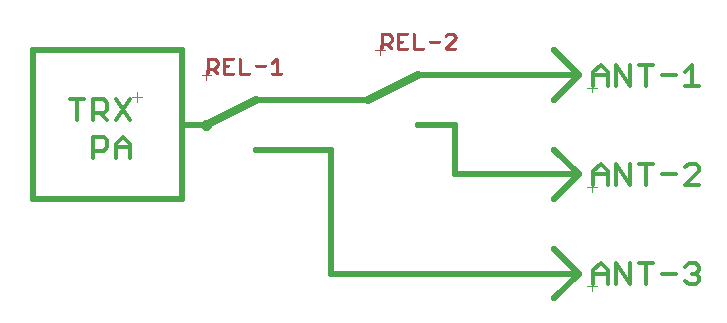
This device supports three measurement couplers, one of these measurement couplers can be additionally connected to relays to connect up to 3 antennas to this coupler. Usually this is done for the shortwave range. So you use measurement coupler-1 for shortwave and connect its output to a relay board. The relays are then switched on automatically depending on the selected band. In combination with the CAT (CI/V) interface a completely automatic antenna switching is possible. Suitable relay boards are described on www.dj0abr.de.
The relay board requires 2 relays, as wired in the picture.
Reverse diodes are not required, they are already present on the board. The relays are connected from connector ANT1 and ANT2 each against +12V.
Note-5: ON/OFF relay for power supply
There are two connections which can switch 12V relays directly (return diode is already present on the board).
POWER SUPPLY ON:
As soon as you turn on the power, this connector goes to GND, so a relay is energized, the controller is in “Standby”. If you switch the controller to “active” to start transmitting, this connection becomes high impedance again, a relay would drop out again.
The reason for this is an important safety function: You connect a relay in latching mode here. In “active” mode this output is dropped out, but because of the latching the relay remains energized. In case of any failure in the power supply, the relay can drop out by itself and is no longer forced to “ON”. So after a fault, the PA remains off and will not turn on by itself.
If you use the DJ0ABR overcurrent fuse board, this connector is connected to the “ON” relay.
POWER SUPPLY OFF:
this connection is high impedance during operation, so a connected relay drops out. In case of an emergency shutdown, the connection goes to GND, so a relay picks up.
If you use the DJ0ABR overcurrent fuse board, this terminal is connected to the “OFF” relay.


