Translations of this page:
DJ0ABR Projects
Symmetric Short Wave Tuner:
Symmetric Short Wave Tuner:
because I like to experiment with various antennas and for portable use you need a good antenna tuner. Since the tuner should also handle the full 750 W continuous power and adjust both asymmetrical antennas and symmetrical antennas via chicken ladder, a self-construction project had to be started. Commercial tuners in this performance class are extremely expensive and still only partially meet my requirements.
The nice thing about do-it-yourself projects is that you (almost) don't have to look at the costs and can therefore make full use of what is not necessary with commercial devices. Nevertheless, this device costs only a small fraction of a finished device in the same class.
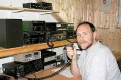
The remote control is especially important. Because this means that the tuner can be installed where it belongs: near the antenna.
A lot of voodoo is spread over and over again via antenna adjustment, although things are quite simple, here is a very simple explanation without formulas (die-hard technicians may forgive the strong simplification):
A precisely matched antenna (R = 50 ohm) does not need a tuner, the transmission power is completely emitted.
If the antenna is not adapted, part of the transmission power is reflected. For example, if the SWR is 1: 2, then 11% of the transmission power is reflected. At 100W transmission power that is 11 watts. These 11 watts go back to the transmitter, where they are largely converted into heat.
If you now connect an adapter between the transmitter and the antenna, this absorbs the reflected 11 watts (as a voltage in the capacitor or as a magnetic field in the coil) and then immediately sends them back to the antenna. No power is lost in the tuner (we will discuss losses below), you can imagine a rubber band that immediately sends the reflected 11W back to the antenna. Of course, 11% of these 11 watts are reflected again at the antenna, i.e. approx. 1 watt, the next time 100mW, etc. Until the process has subsided and all power has been emitted.
Since the reflected power oscillates between the antenna and the tuner, the transmitter does not notice it and “sees” an optimal adjustment.
Ideally, the coils and capacitors in the tuner do not consume any energy. However, some energy is lost in the inevitable resistances of the coil (wire resistance), so the coils are made as large and thick as possible. Inexpensive commercial tuners use toroidal cores (apart from the wire resistance, there are also iron losses in the core material), but our self-built tuner has air coils which are much better and remain practically cold when generously designed (hardly any losses). The capacitors are less of a problem as modern high voltage Cs have high Qs. FKP1 types are very suitable for KW (naturally also mica capacitors, which are however priceless).
Much more important for the losses, however, is the cable connection antenna <> tuner. Because here all the reflected reactive power has to oscillate. The current load is high here and there are usually sheath waves on coax cables. The connection between antenna and tuner must therefore be as short as possible, hence the remote control of our do-it-yourself tuner. As a cable, use a chicken ladder that is as symmetrical as possible. If you have to use coaxial cable, it should hang freely and not touch anywhere, as otherwise the sheath waves radiate into the environment and this energy is lost.
The capacitors and also the layout (conductor tracks) have to withstand high voltages. As an example: 750 watts at a 50 ohm antenna produces a peak voltage of 273 volts, which is still relatively harmless for the capacitors. However, if my antenna has a higher impedance and is therefore adjusted, it looks different. For example, if the antenna has 2000 ohms, the voltage rises to 1.7 kV, which is nothing unusual. Therefore I use FKP1 capacitors with 2kV andalways connect 2 of them in series, which results in a load capacity of up to 4kV. This should be able to safely handle most fitting cases.
At 750 watts at a 50 ohm antenna, 5.4 A (peak) flow. But if you have to adapt a low-resistance antenna (all antennas that are too short), the current would already be 12 A at 10 ohms, for example. Therefore, I have selected 16A types as relays, which are still affordable and allow antennas to be adapted down to approx Ohm.
the project has now been set up and in use, so the following information has been tested in practice.
The tuner consists of 2 boards: the relay board with the coils and high voltage capacitors, as well as the control board.
