Sidebar
Table of Contents
1kW LDMOSFET power amplifier for shortwave
Transmission Line Transformer TLT
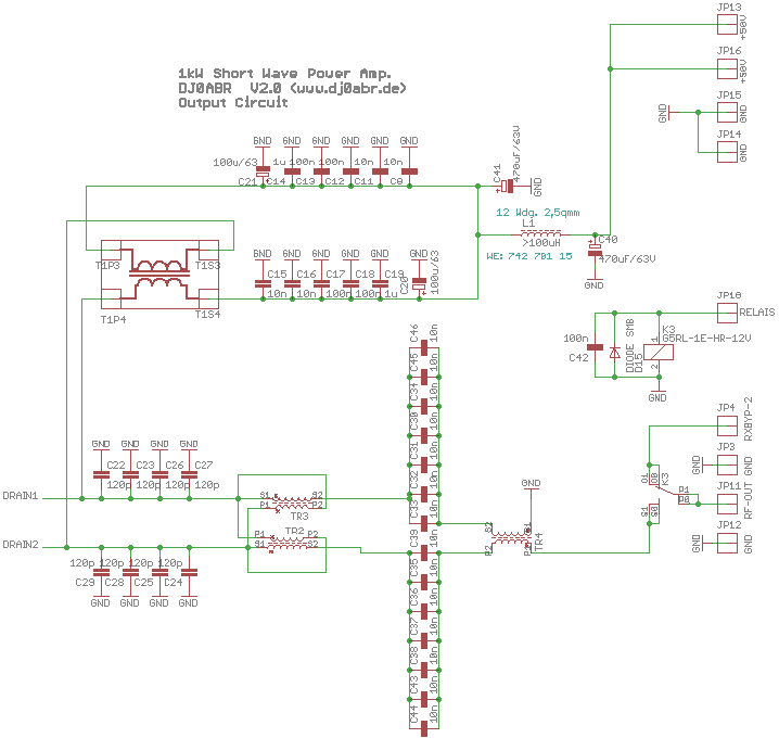
Let's have a look at the output circuit of the power amplifier, namely TR2 and TR3 at the bottom of the picture.
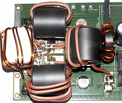
and this is how the practical setup of an older prototype looks like:
The white choke on the left is for the power supply, and to the right is TR3 and TR4. These two tube cores are responsible for the impedance transformation. On the right there is another balun to create an unbalanced output signal.
Transmission line transformer (TLT):
The function of TR3 and TR4 was very mysterious at first. However, the PA works very well, only how was a big mystery to me for a long time.
After the attempt to increase the transformation ratio by an additional number of turns failed (nothing had changed) it was clear that it could not be a “normal” transformer.
An American OM then gave me the idea that it could be a line transformer. A comparison with common designs was also inconclusive. But suddenly it fell like scales from my eyes, I had it all the time in view and yet not recognized: TR3 and TR4 are not simply two transformers, no, TR3 and TR4 are “one” transformer and belong inseparably together. The fact that they are wound on two tube cores makes construction and assembly easier, yet they are a single part.
Knowing this, I compared the circuit again with various basic information and quickly found what I was looking for. It is a balanced line transformer with an impedance transformation ratio of 1:9, which now makes sense and fits with relevant publications.
Because it is balanced, another balun follows with TR4, which itself is a line transformer with a ratio of 1:1.
With this knowledge the power was calculated: P = U²/R
(we are symmetrical, therefore the formula P = U²/2R, which is usually used for push-pull PAs, does not apply here)
R is the antenna impedance of 50 ohms divided by the turns ratio = 50/9 = 5.5 ohms.
The power P = 50² / 5.5 = 455 watts.
What is going on now ? The power amplifier easily brings the allowed 750 watts and not only 455 watts, something is still wrong.
The decisive hint came this time from DK4SX, who already had a nice publication in the Funkamateur about LDMOS. He says that the side of the switched off mosfet adds its energy to the energy of the switched on mosfet. That makes sense, because somewhere this magnetically stored energy has to go eventually. Therefore, one would have to calculate with 100V instead of 50V, but make deductions, so one calculates with 80 volts:
P = 80² / 5,5 = 1163 Watt
And here you come very close to reality. This power can be generated at least on the lower bands with this PA.
The mystery around these two tube cores seems to be solved.
Youtube publications:
Healthy skepticism is appropriate. What some OMs show here cannot be physically. The above circuit cannot generate 1.5kW or even 2kW, yet there are videos which demonstrate exactly that.
My theory for these strange demonstrations is that no output lowpass is used. Thus the harmonics are measured (which can have considerable levels with AB power amplifiers). If one then also “overlooks” the returning power, such unbelievable displays quickly come about.


