Sidebar
Table of Contents
250W PA for DATV via QO-100
This description is for my own documentation only.
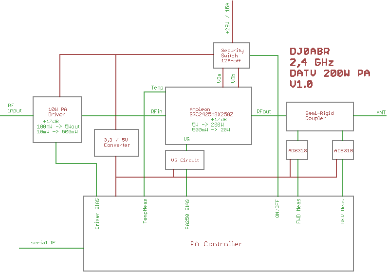
Block diagram:
The following components are used:
1. ampleon 2.4 GHz module BPC2425M9X250Z 2. driver: selfmade 10 W PA, see HERE 3. a directional coupler consisting of two parallel Simirigid cables and two AD8318 modules 4. a controller board for control and monitoring and remote control via RS232 5. various circuits to generate the supply voltages and the BIAS voltages
Structure:
the whole 2.4GHz branch shall be built in its own milled aluminum case with a solid copper bottom. From RFinput to antenna output everything shall be realized without gaps and connectors.
The first work is the production of the aluminum frame and the copper bottom plate. Only when the 2.4 GHz modules are installed, the rest of the work will be done.
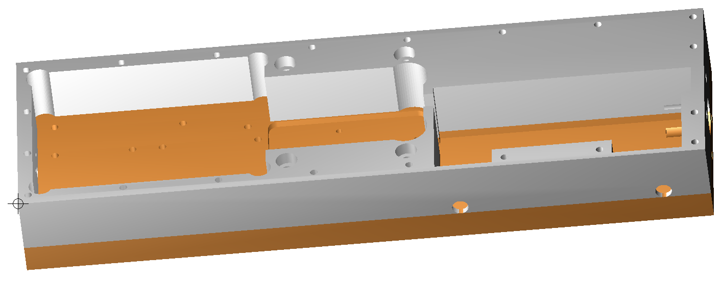
first the cooling case was drawn in 3D with Turbocad:
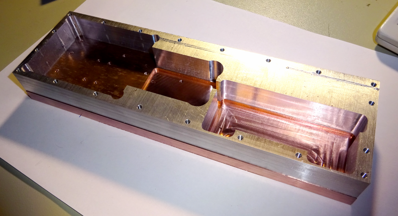
then the milling of the lower copper plate and the aluminum frame took place. Both are screwed together:
before the boards are mounted, the side holes for all connectors have to be milled.
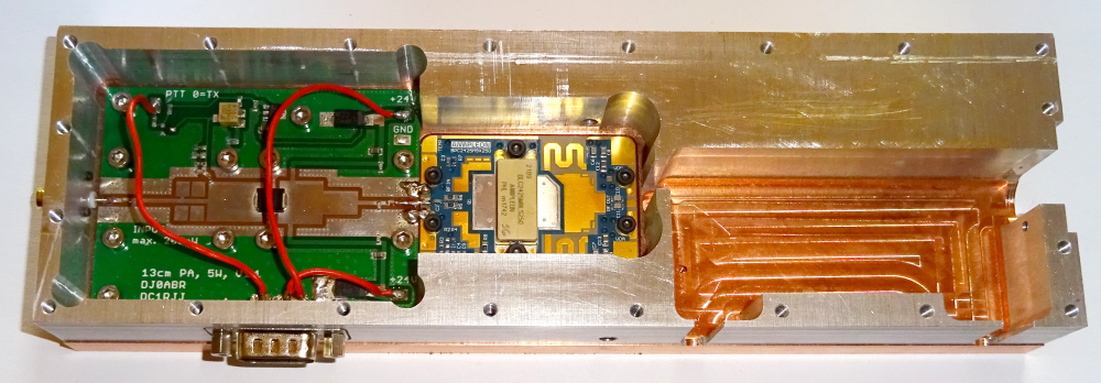
Now all the holes are done, and the 10W driver is mounted and tested.
the 10W driver PA brings as expected 17dB gain at 24V and 100mA quiescent current.
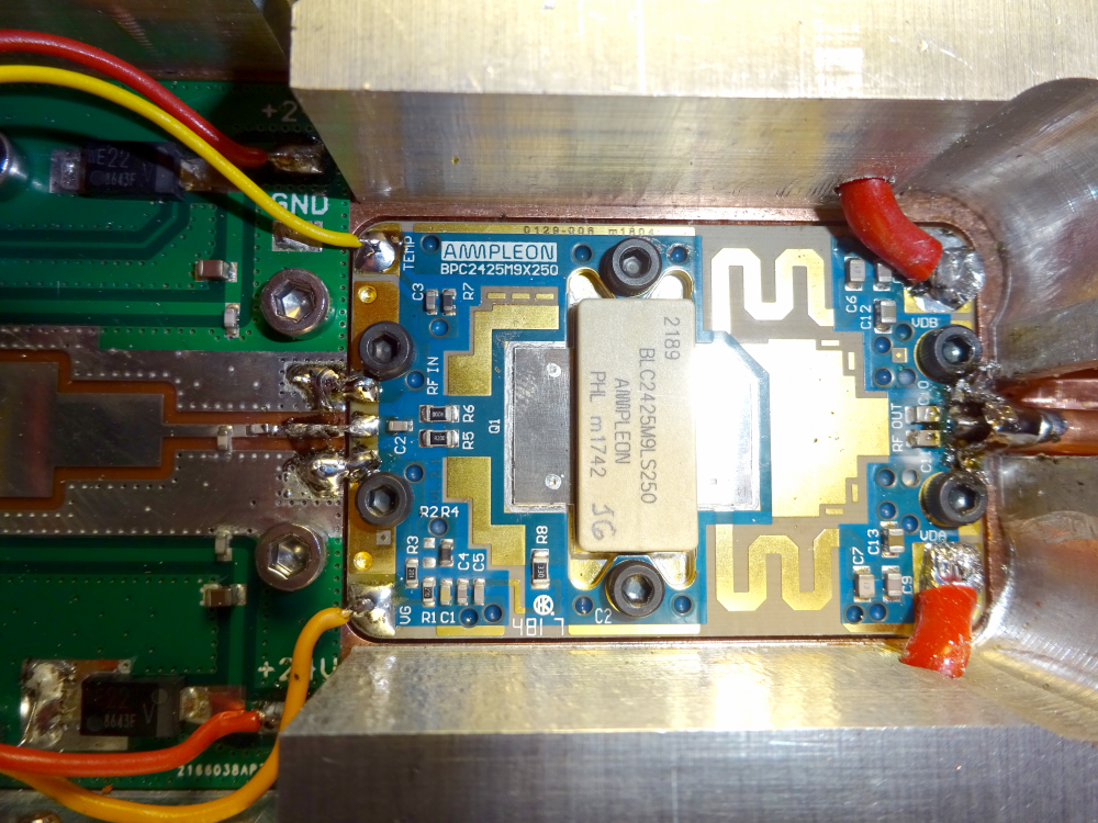
Under the 10W PA is normal white thermal paste. Under the 250W module is special conductive copper thermal paste from the PC area.
and the directional coupler is installed
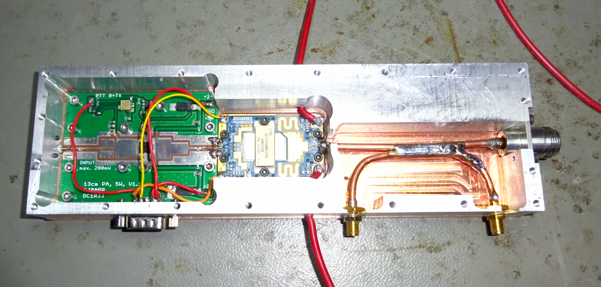
a semi-rigid cable establishes the connection of the PA to the output N-connector. Over a length of about 25mm (exact measurement doesn't matter) this cable is filed down, leaving an open slot about 2mm wide in the copper jacket. The same was done for the bent decoupling semi-rigid cable. Finally, the parts were soldered together so that the slots face each other. This allows some of the output power to couple. A portion of the forward and return power, respectively, is present at the two SMA connectors.
Commissioning
Here are some detailed pictures of the setup:
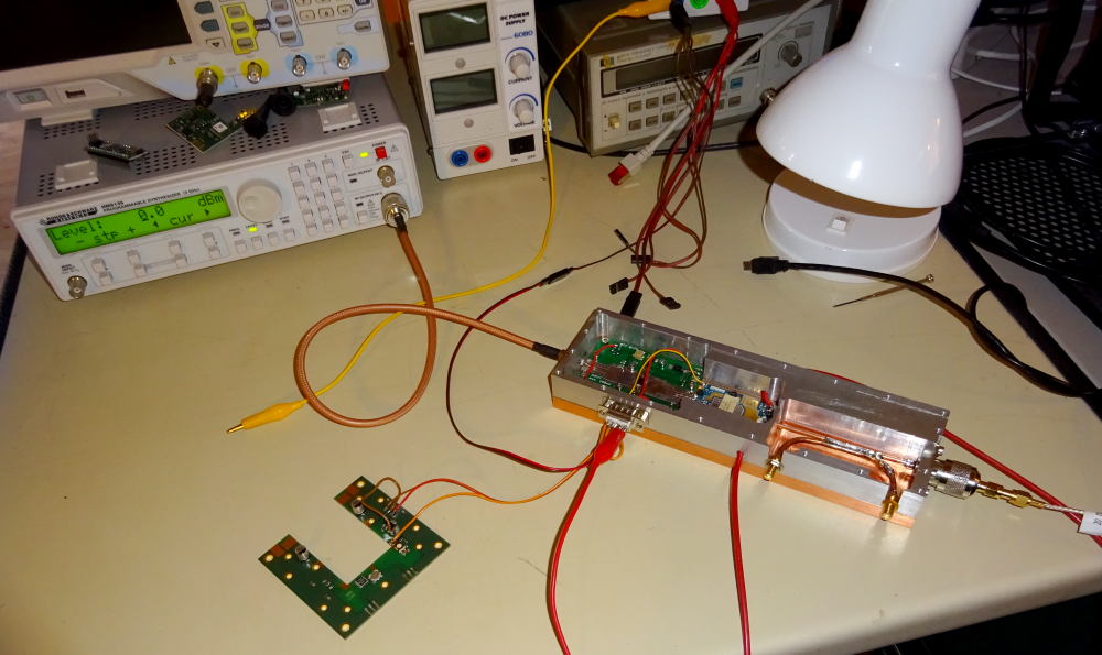
the PA in test mode. The board in front generates the gate bias for the 250W module. This board was designed and built by DG8FAC and is also in the QO-100 station at the Antarctic station. It is a 5V voltage regulator, an analog switch and a potentiometer for quiescent current adjustment. To achieve the desired gain of +17dB in linear mode, a quiescent current of about 800mA must be set.
Detailed view of the PA. Note the 2.4 GHz input and output connectors. Here you really have to work RF-optimally. The connections must be as short as possible. At the output, a “hood” of solder wire was placed around the semi-rigid cable to get a reasonable match as far as possible. At power levels up to 250 watts, any attenuation acts like a heater and can cause damage.
Thanks to these measures, cable and connector losses are less than 0.2 dB. An attenuation of 0.2dB still means a power loss of over 11 watts at full output ! This shows that you really have to work very precisely.
Directional coupler
the task of the directional coupler is to detect a defective antenna in order to be able to switch off the PA quickly. It is not a precision part, it only gives approximate values.
Both SMA connectors must be terminated with 50 Ohm. The connector which is closer to the PA module indicates the output power. The connector closer to the output indicates the returning power.
To measure the coupling loss the PA was driven with 1 Watt output power (+30dBm). At the SMA connector -3dBm was measured, so the coupling loss is 33dB. With the maximum power allowed in DL of 75 watts (48.8dBm), this corresponds to an outcoupling power of 48.8-33 = approx. 15.8dBm which is 38mW. When connecting a detector I have to take this into account and if necessary add an attenuator to avoid overdriving the detector.
After that I measured at the other SMA connector, and it was -15dBm. So the directivity is 12dB. This is not much, but it allows a resolution of 1.7 : 1 for the SWR measurement. This is quite sufficient for this application, because the 250W module can withstand a SWR of 4 : 1 over the whole working range, and this can be detected safely. You just have to provide a fast shutdown, because the module can only withstand such an error for a short time. Therefore I will not use a microcontroller for the emergency shutdown, but switch off the gate voltage directly via the SWR detector which should be done in a few microseconds.
Quiescent current control
The Ampleon module has a NTC which reduces the quiescent current when the temperature rises. This produces a stable operating range. Unfortunately this NTC circuit is only designed for CW pulse operation. In our linear A operation it is completely unsuitable. Even with the slightest increase in temperature, the quiescent current drops extremely and radio operation becomes impossible.
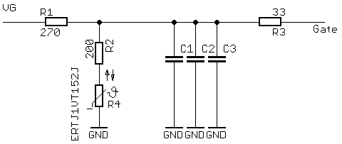
To solve the problem, the NTC circuit was first analyzed:
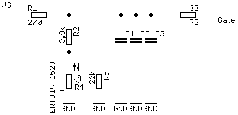
our bias voltage of approx. 1.8 volts is present at the VG connection. When the module temperature rises, R4 becomes less resistive and pulls down the voltage. So the effect of R4 has to be reduced.
First, it is necessary to find out which gate bias voltage is needed at which temperature. To do this, I removed R4 and measured the required gate voltage for a quiescent current of 800mA:
24 degrees C … 2,03V … OnBoard-NTC=14,9k
35 degrees C … 1,99V … OnBoard-NTC=0,64k
so the effect of the NTC must be reduced. This could be done by increasing R2 to about 5k. But there is a free soldering place in the layout for a resistor parallel to R4. Here 22k were soldered to reduce the effect of the NTC. Then a 20k potentiometer for R2 was installed and set to 5k. By heating the heat sink and adjusting the potentiometer, the required value was finally determined: 3.9k.
After installing the resistors the quiescent current was measured at different temperatures, it remains constant.
The circuit on the module now looks like this:
after longer tests with higher temperatures it turned out that the quiescent current does increase slightly with temperature, so the resistor R2 was reduced to 3.3k.
Cooling
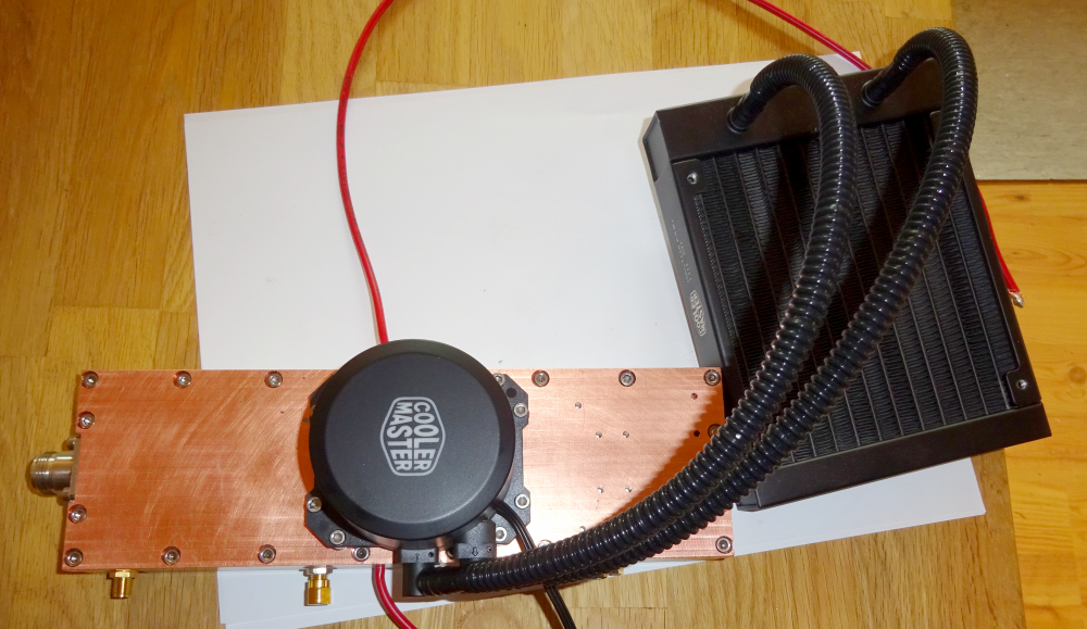
the temperature has to get out of the case. For this I use a PC water cooler. This is screwed to the PA with copper thermal paste, just below the 250W module.

