Table of Contents
CNC warning light
Circuit diagram
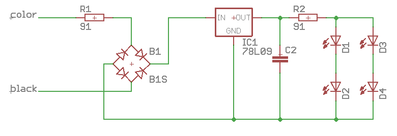
Original circuit diagram. This is an excerpt of the relevant parts, there are more components on it, but they are only responsible for a possible signal generator.
This circuit is identical for each of the colors on the board, and all must be changed equally.
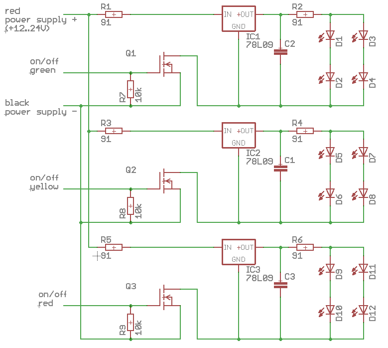
the rectifiers are removed and the black connector becomes negative supply.
All (three) color leads are connected together and become positive supply (so only one + terminal left).


