Table of Contents
Low Power TX Filter
5 Watts
30m, 20m, 17m, 15m, 12m, 10m
This transmission filter has been specifically designed for low power applications as used in WSPR operation. It has been optimized for minimal component requirements and low power consumption. One of its applications is a solar-powered WSPR beacon operating at power levels in the range of several 100mW.
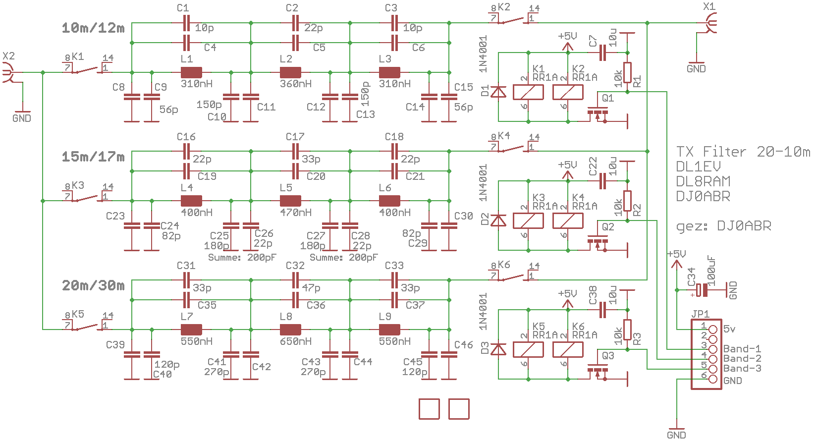
The filter features three filter branches which are switched via reed relays.
The band distribution is as follows:
| Filter Branch | Band |
|---|---|
| 1 | 10m+12m |
| 2 | 15m+17m |
| 3 | 20m+30m |
Naturally, the filter attenuation is stronger on the higher band. However, the required -40dB is also achieved on the lower band, provided that the amplifier has a normal reduction of harmonics.
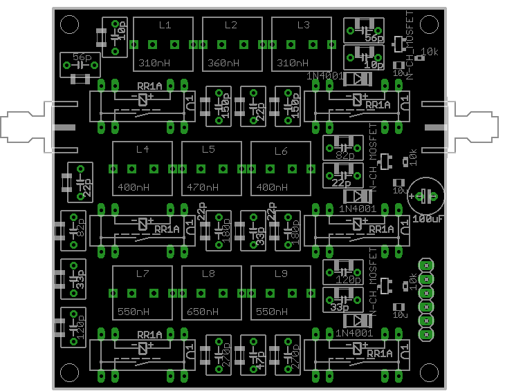
All capacitors in the layout are duplicated, offering two advantages:
the option to solder either SMD or through-hole capacitors the ability to parallel capacitors to create finer values Additionally, capacitors parallel to the coils are provided. Usually, these are not equipped, but in some cases, they can be used to optimize the slope steepness. However, a spectrum analyzer is always required for this.
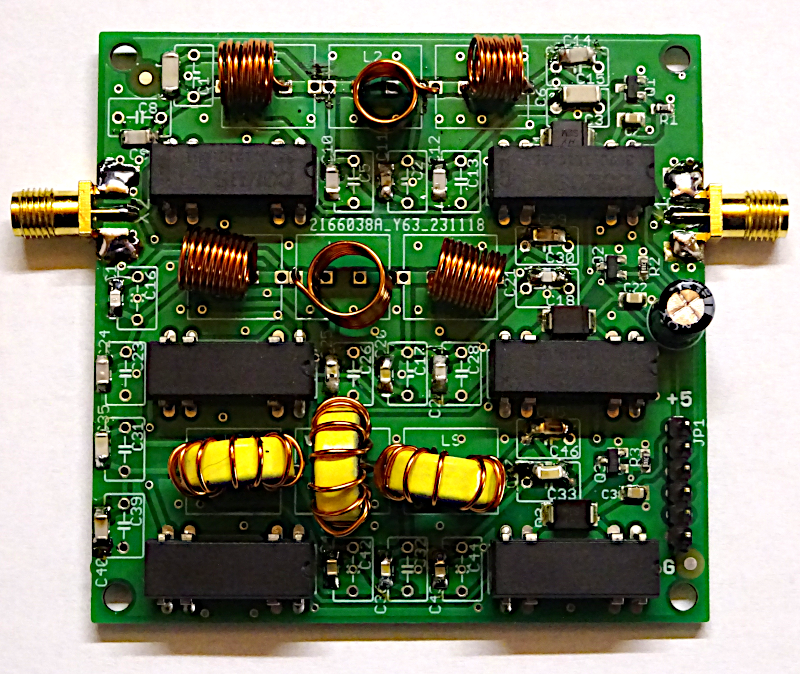
The coils for the filter branches from 17m to 10m are designed as air coils. The wire diameter is 0.63mm. A 6mm and an 8mm drill bit can be used as a winding mandrel. When calculating the inductances, it is important to note that the calculated diameter of the coil is the mandrel diameter + wire diameter, e.g., 6.63mm. This is important if you want to use a different wire and recalculate the coils.
The middle coils of branch 1 and 2 are executed standing to ensure sufficient decoupling. For this reason, an additional half winding is always included in these coils, so they fit well into the holes.
The filter branches are switched with reed relays. The board is designed for a 5V supply. A filter branch is switched on when a voltage greater than 3V is applied to the control input. This also allows control with the usual 3.3V GPIO outputs of microcontrollers.
Winding Data for Inductors
| Coil | Mandrel Diameter | Number of Turns | Coil Length | Orientation | Notes |
|---|---|---|---|---|---|
| L1 and L3 | 6mm | 8 | tightly wound | lying | |
| L2 | 6mm | 9.5 | 10mm | standing | |
| L4 and L6 | 6mm | 10 | tightly wound | lying | |
| L5 | 8mm | 8.5 | tightly wound | standing | use a 7.5mm drill bit as a mandrel, as the winding expands a bit |
| L7 and L9 | T50-6 | 11 | evenly distributed | toroidal core | |
| L8 | T50-6 | 12 | evenly distributed | toroidal core |
Filter Calculation and Dimensioning with RFsim99:
Here are the basic settings for those who want to replicate the calculation with RFsim99:
Chebyshev, 7-pole, parallel, Ripple: 0.01dB
Bandwidth:
10/12m … 36 MHz
15/17m … 27 MHz
20/30m … 18 MHz
Especially the setting of the ripple to 0.01 is of utmost importance for a filter with minimal passband attenuation.\ The exact bandwidths of the filters have been adjusted in the calculation so that standard values for the capacitors are obtained.
The capacitors at the input and output of the filters are to be chosen 10pF smaller than calculated, as traces and relays already contribute 10pF.
The parallel capacitors to the coils are very important to improve the slope steepness. Only this way can a filter branch be used for 2 bands. However, a computational determination of these capacitors was impossible, hence their values were determined empirically.
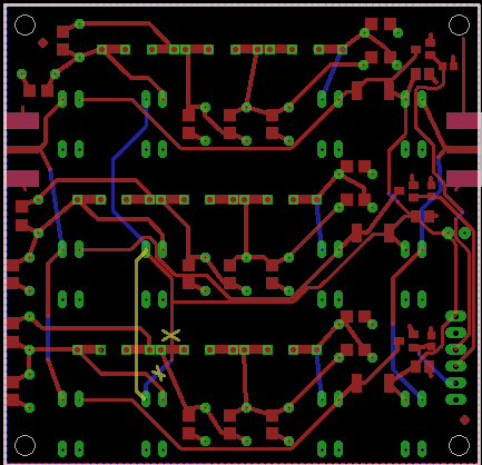
Layout Correction
A mistake crept into the layout:
See the yellow marked changes:
On the top and bottom, a line needs to be cut through.
On the bottom, an insulated line should be laid.
Assembly Plan
Measurement Values
| Filter Branch | Band | Passband Attenuation | 1st Harmonic | 2nd Harmonic | Input SWR |
|---|---|---|---|---|---|
| 1 | 10 m | -0.5 dB | -55 dB | -74 dB | 1.06 |
| 1 | 12 m | -0.4 dB | -41 dB | -62 dB | 1.10 |
| 2 | 15 m | -0.5 dB | -54 dB | -60 dB | 1.12 |
| 2 | 17 m | -0.4 dB | -41 dB | -57 dB | 1.11 |
| 3 | 20 m | -0.3 dB | -63 dB | -71 dB | 1.27 |
| 3 | 30 m | -0.3 dB | -14 dB | -83 dB | 1.15 |
30m is optional and only possible if the PA already has a 1st harmonic at least 26dB below the signal level.


