Table of Contents
250W PA for DATV via QO-100
Modules
Here are the individual modules described which are needed in addition to the PA:
Controller
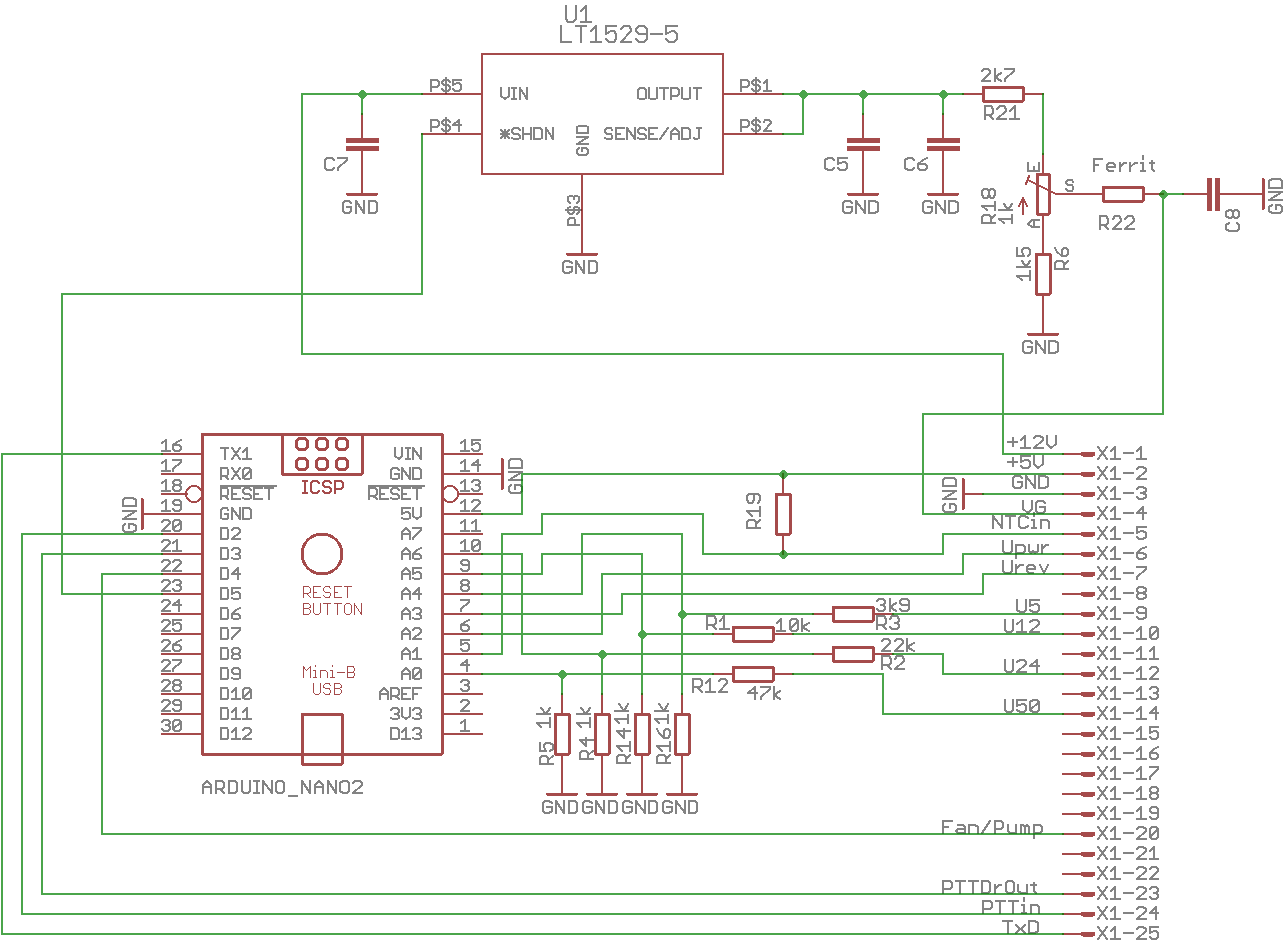
the controller measures all voltages. The 50V phantom power, the 24V PA supply, the 12V and the 5V for the controller and the cooling. It also measures the temperature via the NTC.
If these voltages are ok, the PTT input is monitored. This is connected to my transceiver via a long cable. As soon as the PTT line is pulled, in intervals of 50ms these lines are operated:
* Activation of the gate bias of the transmitter module
* Activation of the PTT line of the driver stage
the PA is now on the air.
The temperature is continuously monitored. As soon as it rises above 40 degrees, the cooling pump as well as the fan are switched on and switched off again when the temperature falls below 37 degrees. During transmission, the pump and fan are always switched on. If the temperature exceeds 60 degrees, it is switched off immediately.
Furthermore, the voltage at the Pwr and Rev sensors is monitored. If the SWR exceeds a value of 2 : 1, the PA is immediately switched off completely.
As uC an Arduino-Nano board is used.
Status messages are output via the serial interface (4800,n,8,1).
The controller is equipped with a watchdog, which detects a program crash. In this case a reset is generated and the controller restarts. If the PTT is pulled during the program start, this is ignored and no transmit operation is started.
The bias voltage is generated with a LT1529-5. This is a 5V voltage regulator which has an on/off connector. Behind the voltage regulator is a potentiometer for setting the PA quiescent current of 800mA.
The board was made by Ernst, DL1EV, on the portal milling machine.
Power / SWR detectors:
As described above, the coupling loss of the directional coupler is 33dB. So at the theoratical maximum power of 250W = 54dBm there is still 21dBm coming out of the coupler. This is for sure too much, but let's have a look at the detectors first.
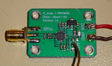
An import board with the ADPZ-8318 is used as power detector.
* according to the datasheet, the chip has an input impedance of 391 ohms at 2.2 GHz. This has to be taken into account later * the maximum input level is -2dBm * the minimum input level is -60dBm * the output voltage is about 0 to 2 volts
first the sensitivity of the original module is measured. This one has a 51 Ohm resistor in parallel to the input, so it has 51 || 390 = 45 Ohm. A bit low, but we will change that.
Without any input signal the module delivers 2.1 volts. With increasing input signal the voltage decreases by 25mV/dB. But this only works at a maximum of -7dBm. After that it becomes noticeably unlinear. So we stay at a maximum of -7dBm.
So an attenuator must be connected upstream, which attenuates by approx. 30dB. Then we have at full power of -9dBm at the input of the detector, which it can measure without problems. But what about at low powers. The detector can still measure -60dBm quite well, below that it becomes non-linear again. So we have 30dB from the attenuator and 33dB from the coupler, which is 63dB attenuation. So we can still reasonably measure 63 - 60 = +3dBm, which is 2mW. So the measurement range goes from 2mW to 250 W, what more do you want.
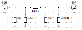
Now we calculate an attenuator with RFsim99:
it was converted to commercial values. Who calculates exactly will see that the attenuator is calculated for 35dB. In practice, however, it has about 30dB, due to coupling of the not ideal layout of the detector. For our purposes, however, it is perfectly ok.
Output voltage: a voltage of 0-2V is applied to the output. The controller works with 1.1V reference, so it can only measure up to 1.1V. Therefore a 1:1 divider is added to the output.
So the output voltage is now 0-1V with a resolution of 12.5mV / dB.


