Table of Contents
250W PA for DATV via QO-100
Overall setup
The PA is installed in a weatherproof installation box. Before that, all assemblies have to be planned as well as a level plan has to be created:
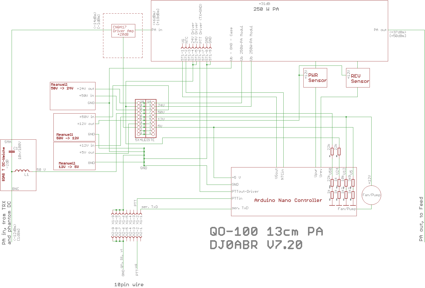
Overall schematic (click to enlarge):
power supply
due to the large distance between shack and PA, the power supply is done with a 50 volt phantom power (this voltage already exists from the KW-PA supply). The voltage is looped into the transmitting coaxial cable in the shack (Aircell-7) and reaches the PA with relatively low impedance.
In the PA three voltage converters (Meanwell) are installed:
* 50V → 24V (set to 27V), 350 watts. Supplies the driver stage and the power amplifier. This DCDC converter can handle less power than the PA, which has some advantages: before the PA transistor gets damaged (by too high current) already the converter switches off. Since in DL only 75 watts on 13cm are allowed anyway, the power of the converter is easily enough.
* 50V → 12V / 2,5A: to supply the some modules and fan/pump of the cooling.
* 12V → 5V / 3A: supplies the controller and some other assemblies
the output of the phantom power is done in the Bias-T at the input. The part is self built and consists only of a 22pF / 500V capacitor (SMD) and a wire coil DM 10mm, 3 Wdg, Cul 1,5mm. The decoupling is quite simple to build, important is only a HF fair construction so that the HF losses are as low as possible. In my case about -2dB (or a little less), it goes also better, I have already managed 0.3dB attenuation. But for the moment it fits.
HF branch SSB and DATV
the HF signal on 2.4 GHz is connected to the lower left. I still have (due to cable attenuation) a signal of 1mW or less here. After DC decoupling it goes to a CN-0417 for level boost to get the correct control level for the PA.
Of course, the efficiency of a 250W PA with only 5W output power is very low, because already the quiescent current consumes about 20 Watts DC. But in return the signal is extremely linear and clean.
The DATV signal is generated by an Adalm-Pluto, preamplified by an Amsat-DL-upconverter (in the shack) to 2.4 GHz and +30dBm power. Due to cable attenuation, a little more than 1mW still arrives at the PA, which matches the correct leveling of the PA.
The levels are calculated to produce up to 20W in SSB mode and up to 60 watts in DATV mode. Especially in SSB this is way too much, so an attenuator is used after the converter in the shack to limit the level to a few watts. In DATV operation, depending on the symbol rate, a power of 10 to 60 watts is required, so here it fits quite well.
Controller
such a PA cannot be operated without a controller. This has the following tasks:
* Monitoring of all supply voltages * Monitoring of the antenna SWR * Measurement of the PA module temperature * Emergency shutdown in case of bad SWR or overheating * Control of cooling (fan/pump) * sending measurement data via serial interface to the shack
the controller and measuring modules are described on a separate page.
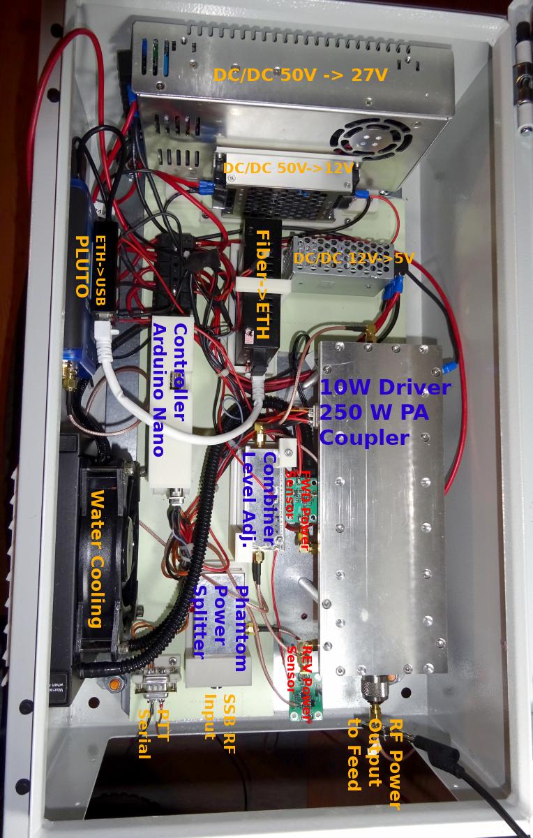
and this is how the finished box looks like:
Addendum
originally I wanted to install the Pluto in the PA box. That doesn't work. The Pluto is so RF sensitive that it cannot tolerate the stray fields from the PA and crashes. It was therefore removed and set up in the shack.

