Table of Contents
Supply voltage and ext. clock for LNBs
If you want to receive QO-100 with a satellite dish, you can connect the LNB to a SDR receiver and receive directly.
However, the LNB needs a supply voltage of up to 14V and also an external precise clock.
To supply power and clock, a simple circuit and a reference frequency, such as GPS, are required.
One of the most popular SDR transceivers is the Adalm-Pluto, which allows transmit and receive operation. Since the orignal TCXO of the Pluto is too inaccurate for QO-100, an external clock of 40 MHz must be used.
The task:
when building up a QO-100 station you always face the same problem to supply these voltages and clocks.
The following things must be available
- a 12 (or 13,8) volt power supply, the usual station power supply is well suitable
- a precise and stable reference frequency, preferably a GPS module with 10 MHz
the following must be provided:
- the power supply must be routed to the LNB via the satellite cable (phantom power supply)
- the 10 MHz must be converted to 40 MHz for Pluto
- the 10 MHz must be converted to 25 MHz for the LNB and then routed to the LNB, either via its own cable or via the satellite cable.
The solution:
to fulfill this recurring task a small and simple circuit board was developed. Relatively few components are used so that even manual assembly is possible without problems.
The board contains all connectors and fits into a standard tinplate case with the dimensions 37x37x30 mm.
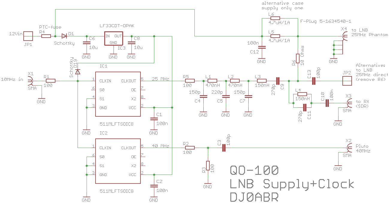
Circuit description:
The usual station power supply of 13.8 (12) volts is applied to the satellite cable via a choke (phantom power). This supplies the LNB and also sets the correct polarity.
A precise 10 MHz reference is connected to X1, e.g. a GPSDO, an OCXO or Rubidium module, etc.
A 511MLFT clock converter is used to generate the 40 MHz reference needed for the Pluto. The two 100 Ohm resistors reduce the level and provide some matching.
Another 511MLFT is wired to generate 25 MHz. Terminals S0 and S1 specify the output frequency. The 25 MHz output signal (3.3V square wave) is filtered and also applied to the satellite cable via R6. If you don't want to install a decoupling element in the LNB, you can also tap the 25 MHz at JP2 and lead it to the LNB via a separate cable.
Layout:
will be added as soon as this circuit is tested sufficiently well.
