HAM radio controller for the Raspberry PI
Power supply
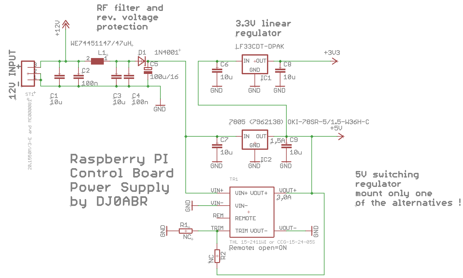
A single supply connection for all components, including the computer. Additional plug-in power supplies are not required.
Supply voltage: 8 to 20 volts (e.g. the usual 13.8V power supply in the shack or in the car) Current consumption: (at 12V) average 0.15A (depending on SBC), in peaks up to 1A
From the input voltage of 8-20V, 5V (via DC / DC converter) and 3.3V (from the 5V via series regulator) are generated internally.
The supply input has a reverse polarity protection diode and can withstand voltages of up to 30 volts. It should be noted that capacitors with the desired dielectric strength are also installed.
The layout is prepared for two alternative DC / DC converters (5V output). The inexpensive one up to 5V / 1A and a high-quality one up to 2A which delivers 5.1V instead of 5V. This is interesting for Raspberry PIs, as they can already report undervoltage at “only” 5V.
Circuit description:
ST1 is the connection for the power supply. The minimum voltage is approx. 8 volts. The maximum voltage depends on the DC / DC converter used and is approx. 30V (see data sheets). It is important, however, that the capacitors in the input can also withstand this voltage.
D1 is a protection diode against polarity reversal. The larger electrolytic capacitor C5 after the diode is very important to make the input voltage sufficiently low against current fluctuations.
IC2 … a very inexpensive DC / DC converter that delivers up to 1.5A at 5V. Alternatively, the following can be fitted:
TR1 … a high quality converter from Traco Power that delivers 2A. If you want to operate a Raspberry PI 4, this converter is advisable.
IC1 generates 3.3V from the 5V. Since no special performance is required here, a series regulator is used which is only slightly cooled by the circuit board.
