CNC Pendant
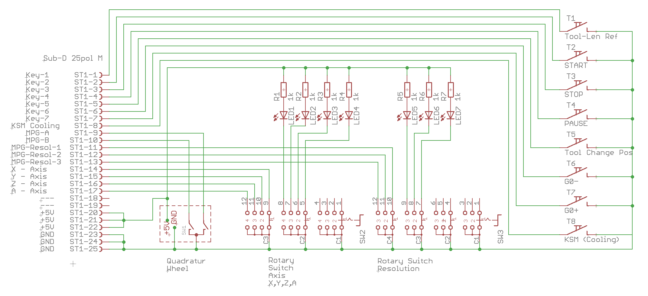
Circuit diagram
Both devices V1 and V2 have identical control elements, only V2 has an additional display.
An optical rotary encoder is used for fine adjustment of the axes. For fast movement there are the keys G0+ and G0-.
A rotary switch is used to select the axis (X, Y, Z or the 4th axis A). With a second rotary switch the speed is selected.
The 8 keys can be assigned in principle arbitrarily, with us they have the following functions:
- Automatic: Start
- Automatic: Pause/Continue
- Automatic: Stop
- Reference the tool length
- Move to the tool change position
- Coolant on/off
- Fast speed G0 +
- Fast speed G0 -
the pinout must of course match the GPIO information in the HAL files.
Display
this circuit is very simple. It consists of a 2.8'' TFT color display with SPI connector and an ESP8266 WiFi controller.
The connection of the two is described here: TFT SPI Display
Just connect the +5V and GND and the display is ready to use.
Before flashing the controller, please read the instructions here: firmware
