Table of Contents
CIV Icom-CAT Interface Router
This project is interesting for everyone who owns more than one ICOM transceiver.
Overview
ICOM uses the CIV interface for remote control of practically all station transceivers. This is a bidirectional serial interface that can transmit both data directions over just one line. It also allows several transceivers to be connected in parallel, as each device can be clearly addressed via its own CIV address.
The possibility of operating many transceivers in parallel on the CIV connection is a huge advantage, but it also harbors two serious problems:
1. If many CIV compatible devices are connected, the risk of data collisions increases, which makes the transmission unreliable and data packets are repeatedly lost.
2. If something faulty happens at a CIV connection (e.g. overvoltage), all connected devices are affected, and that can be very expensive.
Especially point 2) was decisive for the development of the CIV router, because I connected my antenna tuner to the CIV interface and this is 70m away from the shack. Overvoltage from a nearby thunderstorm could destroy all devices.
Point 1) was solved with an algorithm that can also be found in Ethernet network switches: Packets are only delivered to the recipient's interface, other interfaces remain unaffected.
Functions of the CIV router:
      Independent CIV interfaces: 7
      Protection of the inputs: 2-way TVS diodes
      special protection of the inputs for external devices: optocoupler
      additional protected RS-232 interface
      Collision protection with FIFO data buffer
      intelligent data forwarding only to addressed devices
Independent CIV interfaces:
While looking for an easily obtainable microcontroller with as many serial interfaces as possible, I came across the ATXmega128A3. This has 7 serial ports and is therefore ideally suited. Its memory is easily sufficient for the desired function. The smaller type would also be sufficient, since this costs just as much, so I opted for the 128.
Protection of the inputs: 2-way TVS diodes:
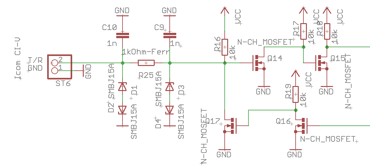
this is how the CIV connections look like:
 There are two anti-parallel TVS diodes directly at the connection. At the same time the input is HF-filtered with two 1nF Cs and one ferrite. Since a possible overvoltage pulse behind the ferrite is already significantly reduced, two more TVS diodes follow here, which dissipate the rest. I equipped two of the connections like this. The CIV connections, which are connected to transceivers over a short distance, do not have TVS diodes.
special protection of the inputs for external devices: optocoupler
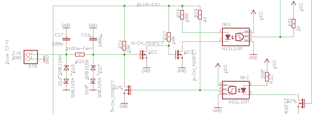
I executed an input like this:
 after the separation of RX and TX, the data is passed through optocouplers. The supply voltage on the left is generated with an isolating DCDC converter. There is of course no 100% separation, since the mass of a radio station is always common everywhere. But everything else is decoupled.
I use this special CIV connector for the external antenna tuner, which is mounted outdoors near the antenna.
additional protected RS-232 interface:
this has nothing to do with CIV, but an RS-232 interface protected by optocouplers is very often needed, in my case for remote control of the antenna tuner.
That's why I have planned this right here:
 This circuit is also equipped with plenty of TVS diodes and HF filters. After converting the voltage level to TTL level, I also access the data with the uC to let an activity LED flicker as soon as data traffic takes place on the RS-232.